Integrated co-fired inductor and preparation method thereof
A technology of co-firing and inductance, which is applied in the field of inductance, can solve the problems of reducing effective magnetic permeability, insufficient molding precision, and increasing process cost, etc., and achieves the effects of improving temperature stability, increasing anti-saturation ability, and reducing vibration and noise
- Summary
- Abstract
- Description
- Claims
- Application Information
AI Technical Summary
Problems solved by technology
Method used
Image
Examples
Embodiment 1
[0079] This embodiment provides a method for manufacturing an integrated co-fired inductor, and the method includes the following steps:
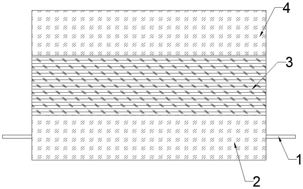
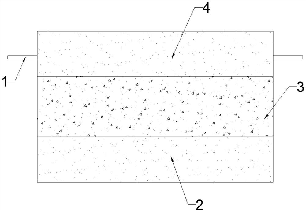
[0080] (1) Fill the mold cavity with 0.2g of the first magnetic powder, remove the enamelled wire from a flat copper wire 1 with a rectangular cross-section and place it on the surface of the first magnetic powder. , the length is 14mm, the width is 2.6mm, and the thickness is 0.3mm. The cavity is oscillated, the wire 1 is embedded in the first magnetic powder, and the first magnetic powder is smoothed; then 0.6g of the second magnetic powder is filled into the cavity, and the cavity is oscillated. Smooth the second magnetic powder; finally fill the mold cavity with 0.2g of the first magnetic powder, oscillate the mold cavity, and smooth the first magnetic powder;
[0081] (2) Mold the magnetic powder filled in the mold cavity, the molding method is hot pressing, and the hot pressing pressure is 300Mpa / cm 2 , the hot-pressing temperature i...
Embodiment 2
[0091] This embodiment provides a method for manufacturing an integrated co-fired inductor, and the method includes the following steps:
[0092] (1) Fill the mold cavity with 0.3g of the first magnetic powder, vibrate the mold cavity, and smooth the first magnetic powder; then fill in 0.5g of the second magnetic powder, remove the enamelled wire of a flat copper wire 1 with a rectangular cross section and place it on the second On the surface of the magnetic powder, both ends of the wire 1 extend out of the mold cavity. The shape of the wire 1 is S-shaped, with a length of 10mm, a width of 2.6mm, and a thickness of 0.30mm. The mold cavity is oscillated, and the wire 1 is embedded in the second magnetic powder, and the second magnetic powder is smoothed. ;Finally fill in 0.3g of the first magnetic powder, vibrate the mold cavity, and smooth the first magnetic powder;
[0093] (2) Mold the magnetic powder filled in the mold cavity, the molding method is hot pressing, and the ho...
Embodiment 3
[0103] This embodiment provides a method for manufacturing an integrated co-fired inductor, and the method includes the following steps:
[0104] (1) Fill the mold cavity with 0.2g of the first magnetic powder, vibrate the cavity, and smooth the first magnetic powder; then fill in 0.6g of the second magnetic powder, vibrate the mold cavity, and smooth the second magnetic powder; finally fill in 0.2g of the second magnetic powder A magnetic powder, a flat copper wire 1 with a rectangular cross-section is placed on the surface of the first magnetic powder after the enameled wire is removed, and the two ends of the wire 1 protrude from the mold cavity. mm, oscillating mold cavity, wire 1 embedded in the first magnetic powder, smoothing the first magnetic powder;
[0105] (2) Mold the magnetic powder filled in the mold cavity, the molding method is hot pressing, and the hot pressing pressure is 400Mpa / cm 2 , the hot-pressing temperature is 180°C, and the hot-pressing time is 30s;...
PUM
| Property | Measurement | Unit |
|---|---|---|
| width | aaaaa | aaaaa |
| thickness | aaaaa | aaaaa |
| current | aaaaa | aaaaa |
Abstract
Description
Claims
Application Information
 - R&D
- Intellectual Property
- Life Sciences
- Materials
- Tech Scout
- Unparalleled Data Quality
- Higher Quality Content
- 60% Fewer Hallucinations
Browse by: Latest US Patents, China's latest patents, Technical Efficacy Thesaurus, Application Domain, Technology Topic, Popular Technical Reports.
© 2025 PatSnap. All rights reserved.Legal|Privacy policy|Modern Slavery Act Transparency Statement|Sitemap|About US| Contact US: help@patsnap.com


