Automatic condensate water discharging device of onboard evaporator

An automatic discharge and evaporator technology, applied in evaporator/condenser, refrigerator, refrigeration components, etc., can solve problems such as difficulty in condensing water discharge, and achieve the effect of improving functional performance and increasing comfort

Active Publication Date: 2021-02-26
XINXIANG AVIATION IND GROUP
View PDF5 Cites 1 Cited by
  • Summary
  • Abstract
  • Description
  • Claims
  • Application Information

AI Technical Summary

Problems solved by technology

[0004] Purpose of the invention: In view of the above problems, design an automatic discharge device for condensed water of an onboard evaporator to solve the technical problem that the condensed water of the onboard evaporator is difficult to discharge under the negative pressure environment generated by the evaporating fan inside the evaporator

Method used


Image

  • Automatic condensate water discharging device of onboard evaporator
  • Automatic condensate water discharging device of onboard evaporator
  • Automatic condensate water discharging device of onboard evaporator

Examples


Embodiment 1

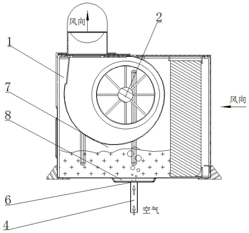
[0043] Embodiment 1, see attached figure 1 , 2, 5-8, providing an on-board evaporator condensate automatic discharge device, including an evaporator shell 1, an evaporating fan 2, a vent pipe 3, a drain pipe 4 and a valve body 5;

[0044] The evaporation fan is installed in the shell of the evaporator, which can form a negative pressure area 7 when drawing air; the lower part of the negative pressure device is a water storage pool 8;

[0045] The upper end of the ventilation pipe penetrates into the evaporator shell, and the upper end of the ventilation pipe is in a negative pressure area;

[0046] The water storage tank is provided with a water hole 6, and the upper end of the drainage pipe is connected to the water hole, and the water hole is in a negative pressure zone;

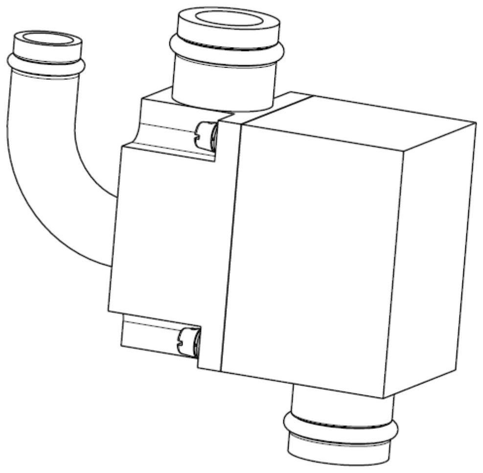
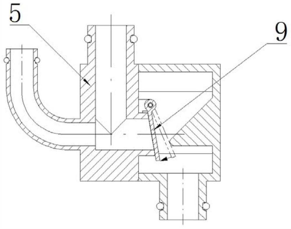
[0047] The valve body is provided with two upper nozzles and one lower nozzle, and the two upper nozzles and one lower nozzle communicate with the inner cavity of the valve to form a three-way structure, ...

Embodiment 2

[0053] Embodiment 2, see attached Figure 1-8 , providing an on-board evaporator condensate automatic discharge device, comprising an evaporator shell 1, an evaporator fan 2, a ventilation pipe 3, a drain pipe 4 and a valve body 5;

[0054] The evaporation fan is installed in the shell of the evaporator, which can form a negative pressure area 7 when drawing air; the lower part of the negative pressure device is a water storage pool 8;

[0055] The upper end of the ventilation pipe penetrates into the evaporator shell, and the upper end of the ventilation pipe is in a negative pressure area;

[0056] The water storage tank is provided with a water hole 6, and the upper end of the drainage pipe is connected to the water hole, and the water hole is in a negative pressure zone;

[0057] The valve body is provided with two upper nozzles and one lower nozzle, and the two upper nozzles and one lower nozzle communicate with the inner cavity of the valve to form a three-way structure...


PUM


Abstract

The invention relates to the technical field of airborne evaporation cycle refrigeration, in particular to an automatic condensate water discharging device of an onboard evaporator. The device comprises an evaporator shell, an evaporation draught fan, a ventilation pipe, a water drainage pipe and a valve body; a three-way structure is formed in an inner cavity of the valve body; and a valve plateis rotatably arranged in the inner cavity of the valve body. When the evaporation draught fan forms air exhaust negative pressure, the valve plate seals the lower end of the ventilation pipe and the lower end of the water drainage pipe; and when the evaporation draught fan does not work, the valve plate is in a free rotating state. By the adoption of the automatic condensate water discharging device of the onboard evaporator, electric energy is not consumed, the installation space on a machine is not increased, condensed water of the machine-mounted evaporator can be automatically discharged,the situation that condensed water is smoothly discharged out of the evaporator in a negative pressure environment is guaranteed, the influence of the negative pressure in the evaporator on condensedwater discharging is reduced, and the functional performance of the evaporator is improved; and meanwhile, the condensate water is prevented from entering a cabin due to unsmooth discharge to influence the safety of other equipment on an aircraft, and the comfort of passengers in the cabin is improved.

Description

technical field [0001] The invention relates to the technical field of onboard evaporative cycle refrigeration, in particular to an automatic discharge device for condensed water of an onboard evaporator. Background technique [0002] The evaporator is one of the four essential components of the airborne evaporative cycle refrigeration system. The evaporative refrigeration cycle technology is used to evaporate the refrigerant in the evaporator core to cool the air passing through the evaporator, and use the evaporator fan to The low-temperature air is sent to the cabin to achieve the purpose of cooling. In order to reduce the temperature and humidity of the air in the cabin, the evaporator must have sufficient cooling and dehumidification capacity. Due to the large pressure difference between the front and rear of the evaporator core, a negative pressure chamber is formed in the air duct from the back of the evaporator core to the blower, resulting in condensation. The wate...

Claims


Application Information

Patent Timeline
Patent Type & Authority Applications(China)
IPC IPC(8): F28F17/00F25B39/02
CPCF28F17/005F25B39/02
Inventor 郭豪凯杨冰洁王沨莉张洋汪智慧王振东李媛媛张爱民姚英丽张雪平
Owner XINXIANG AVIATION IND GROUP
Why Eureka
Try Eureka