
Neck end for a filler neck

a technology of filling neck and filling end, which is applied in the direction of closures, lids, packaging, etc., can solve the problems of unsuitable type of fuel flowing severe damage, and inability to introduce the pump nozzle further into the filling end, etc., to achieve the effect of improving protection

Active Publication Date: 2011-05-12
GERDES
View PDF14 Cites 35 Cited by
  • Summary
  • Abstract
  • Description
  • Claims
  • Application Information

AI Technical Summary

Benefits of technology

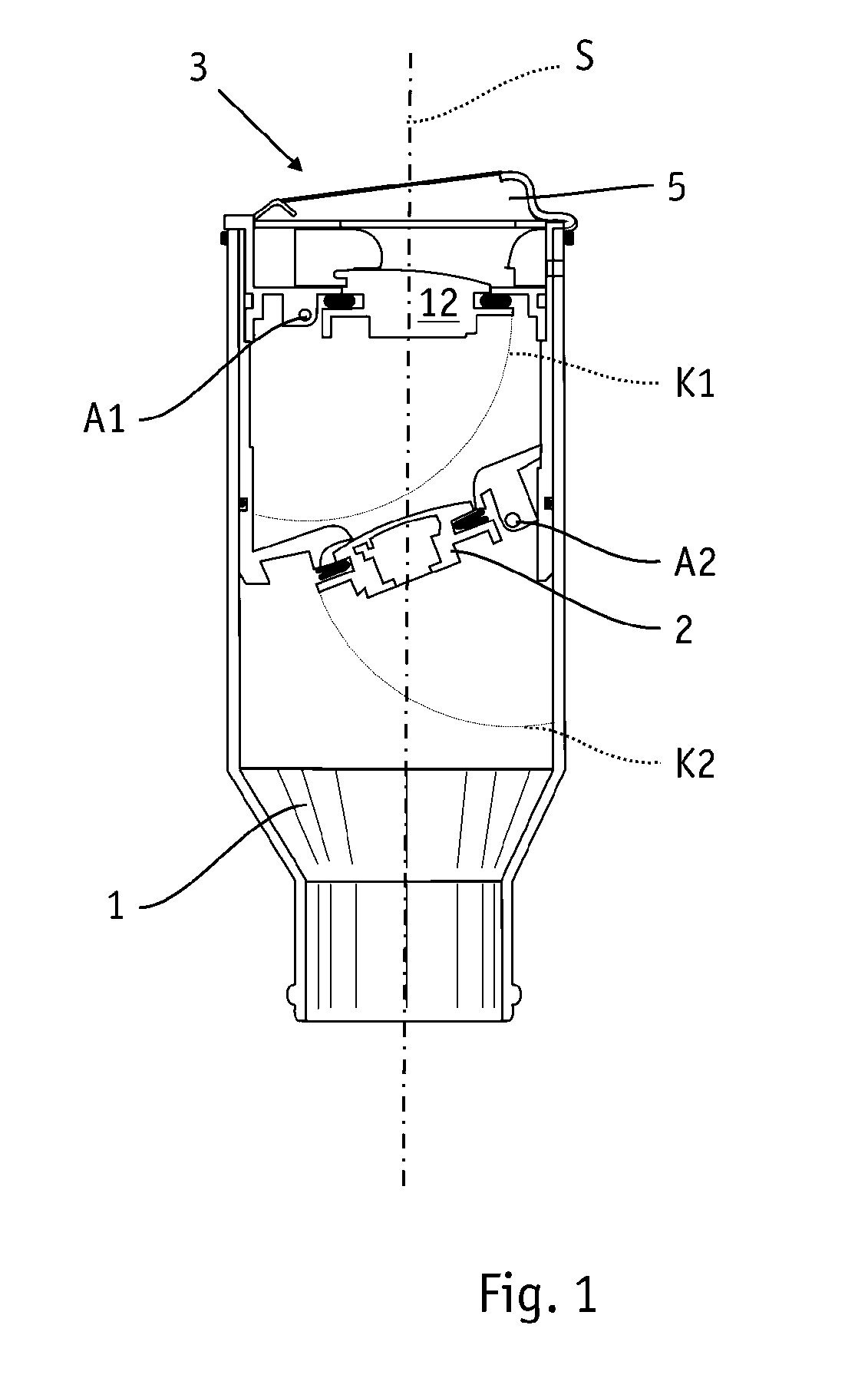
[0024]Thanks to the highly placed lower sealing flap there is still enough space to activate the deactivation function of the pump nozzle when the output pipe is not introduced deeply enough. On the other hand, space obtained below the lower sealing flap can be used either to reduce the installation space of the neck unit or and possibly also to provide an anti-theft means.
[0026]A second aspect of the invention is that of the improved protection from pumping out or extracting the container contents. This is achieved according to the invention by a mechanical barrier which is arranged below the lower sealing flap. This anti-theft means allows liquid through, so it does not impede filling up. However, it prevents pipes or hoses from being inserted so far into the tank that they dip below the liquid level and make it possible to extract liquid.

Problems solved by technology

In particular in the case of modern engines, it is increasingly important to ensure the correct type of fuel, as for example modern injection systems in common rail diesel injection are lubricated by the lubricant content of the diesel fuel and can suffer severe damage even after a short operating time with petrol.
As a result, the hooks at least cannot all be displaced outwards if a pump nozzle which is too small is inserted, in which case the lower part of the pump nozzle engages with the end regions of the hooks which are not pushed outwards, so that the pump nozzle cannot be introduced further into the neck but snags.
Although this neck provides the possibility of preventing incorrect filling, it has the disadvantage that although the pump nozzle cannot be introduced completely into the neck, filling of the neck with at least a small amount would still be possible with corresponding disregard of the safety instructions, because no cap is blocked with the safety elements, only the pump nozzle is prevented from being inserted into the neck.
This does not however prevent the filling function of the snagged, excessively small pipe of the pump nozzle from being operated, with the result that fuel of an unsuitable type then flows into the neck.
A further disadvantage of this configuration consists in that the displacement of the hooks requires a lot of mechanical effort, which results in unreliable functioning.
Over time, the neck end can be damaged in this manner, in particular if the user of the vehicle tries to force the pipe of the pump nozzle in.
This configuration firstly has the disadvantage that the pump nozzle rests directly on the lower covering flap, that is, acts on the actual closure flap of the neck.
If attempts are then made to fill up with the “wrong” pump nozzle, this can cause damage to this sealing flap as a result of the pressure on the lower covering flap, which is not unlocked.
A further disadvantage of this configuration is that tilted, oblique placement of the pump nozzle can likewise cause unlocking although the diameter of the pipe of the pump nozzle is actually too small.
Furthermore, the engagement of the lower covering plate in the groove of the displacement element is comparatively prone to faults, as this groove can become damaged or disengaged for example owing to dirt or wear as a result of the regularly occurring lateral sliding of the pipe in the displacement element.
In this case, however, the safety function is cancelled, with the result that the lower cover can be tilted downwards even with smaller pipe diameters.
A further disadvantage of this configuration consists in that the safety means also allows the nose of an unsuitable pump nozzle to be inserted comparatively deeply before the driver can establish that the pump nozzle does not actually fit into the neck.
Many users will however not realise this, but will instead think that this is normal for this configuration, that the pipe section of the pump nozzle cannot be completely sunk, or will assume that the neck is defective.
This can result in this user either continuing to push with force or starting to fill up, which then in turn results in the petrol flowing into the region between the upper edge of the neck end and the lower cover and flowing from there either into the fuel supply through the legally required return line to the tank or into the reserve tank.
Although this solution provides reliable sealing and sufficient protection from incorrect filling, it has the disadvantage, as in the other, above-described solutions, that the thickened end region of the pipe neck which must receive the capless mechanism must be relatively long to be able to accommodate the mechanical functional elements.
This in turn results in a larger space requirement for the pipe neck, which is not always available, depending on the vehicle design and in particular with subsequent conversion from a conventional to a capless neck with an otherwise unchanged vehicle design.
A further disadvantage of the prior art is the fact that the capless necks are not sufficiently secure from the introduction of a drainage hose with the intention of theft.

Method used


Image

  • Neck end for a filler neck
  • Neck end for a filler neck
  • Neck end for a filler neck

Examples


Embodiment Construction

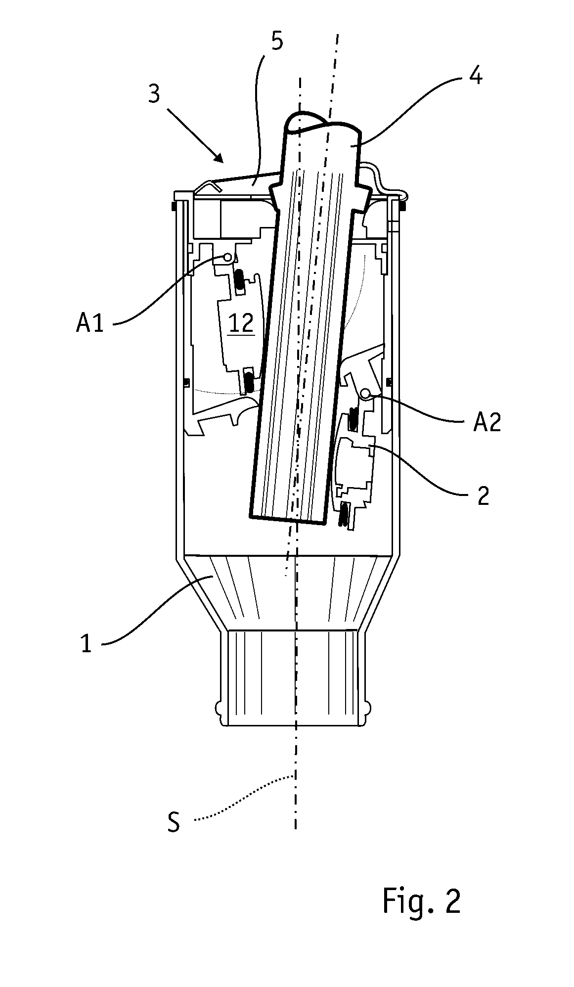
[0041]FIGS. 1 and 2 show a neck end according to the invention for the filling neck of a container. Such a container can be the tank of a motor vehicle, as in the exemplary embodiment shown. This container has a double-flap closure which is formed by the upper pivoting flap 12 and the lower sealing flap 2. The neck insert has a widened diameter in the region of the flaps compared to the lower section of the filling neck 1, to be able to receive the closure mechanism and to be able to introduce the filling pipe 4 of a pump nozzle as shown in FIG. 2. The filling neck 1 extends along a straight or curved neck axis S and conducts the introduced fuel into the tank of the motor vehicle.

[0042]As in the exemplary embodiment shown, the neck end can be in two parts, an inner plug-in pipe which bears the closure mechanism being inserted into an outer retaining pipe of the filling neck 1. Seals arranged between the two components ensure that a gastight and fluid-tight connection is realised. Th...


PUM


Abstract

The invention relates to an in particular capless neck end for a container, in particular a fuel container, with a double-flap closure which is formed by an upper pivoting flap (12) and a lower sealing flap (2). Neck ends of this type are known from WO 2006 / 084908. These known neck ends require too much installation space and are not optimally protected from the contents of the container being pumped out. This is improved by the invention in that the lower sealing flap is arranged in such a manner that it is arranged at an angle to the transverse section plane arranged at right angles to the neck axis (S) when in the closed state, and either the articulation point or, when in the closed state, the end opposite the articulation point of the lower sealing flap is arranged above the lower end of the first circular segment path. Furthermore, an anti-theft means (25) in the form of a mechanical barrier is provided below the double-flap closure.

Description

CROSS REFERENCE TO RELATED APPLICATIONS[0001]The present application claims priority to PCT International Application No. PCT / EP2009 / 055682 filed on May 11, 2009 which claims priority to German Patent Application Serial No. DE 10 2008 022 912.1 filed on May 9, 2008.STATEMENT RE: FEDERALLY SPONSORED RESEARCH / DEVELOPMENT[0002]Not Applicable.BACKGROUND[0003]1. Technical Field of the Invention[0004]The invention relates to a neck end for a filling neck of a container, in particular a tank of a motor vehicle, with a pipe piece and a closure mechanism which has an upper pivoting flap arranged in the pipe piece and a lower sealing flap arranged thereunder, wherein the upper pivoting flap and the lower sealing flap are articulated about an articulation point on one side of the pipe neck, and in each case the upper pivoting flap can be opened with its end opposite the articulation point along a first circular segment path as a result of a pivoting movement about the articulation point by the...

Claims


Application Information

Patent Timeline
IPC IPC(8): B65D51/04
CPCB60K15/04B60K15/0403B60K2015/0483B60K2015/0445B60K2015/0429
Inventor GERDES, RALF
Owner GERDES
Learn More