Flange mechanism

A technology of flanges and flanges, which is applied to the parts of grinding machine tools, manufacturing tools, sawing machine devices, etc., and can solve the problem that the fixing nut cannot be disassembled

Pending Publication Date: 2021-02-26
DISCO CORP
View PDF7 Cites 0 Cited by
  • Summary
  • Abstract
  • Description
  • Claims
  • Application Information

AI Technical Summary

Problems solved by technology

[0006] Furthermore, when sewage infiltrates into the threaded part of the fixing nut and the fixing flange and the water dries thereafter, there is a fear that cutting chips will stick between the threads of the screwing part to cause contamination, and the fixing nut cannot be detached from the rear flange.

Method used


Image

  • Flange mechanism
  • Flange mechanism
  • Flange mechanism

Examples


Embodiment Construction

[0023] Hereinafter, one embodiment of the present invention will be described with appropriate reference to the drawings.

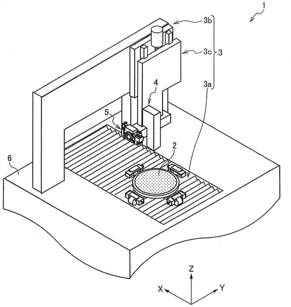
[0024] figure 1 The cutting device 1 is shown by image 3 The shown flange mechanism 30 is a machining device that cuts a workpiece with the cutting tool 20 clamped and fixed.

[0025] Such as figure 1 As shown, the cutting device 1 is configured to include a chuck table 2 , a moving member 3 , an imaging member 4 , and a cutting member 5 . Although the workpiece is not particularly limited, it is, for example, various plate-shaped processing materials such as plate-shaped semiconductor wafers, optical device wafers, plate-shaped inorganic material substrates, and plate-shaped ductile materials. In this embodiment, a case where a plurality of mutually perpendicular dividing lines are formed on the front surface of the workpiece will be described.

[0026] The chuck table 2 attracts and holds the workpiece. The chuck table 2 is formed in a disc shape,...


PUM


Abstract

Provided is a flange mechanism capable of preventing cutting chips from penetrating and adhering to a screw member as contaminants, and preventing a fixing part that fixes a cutting tool from being unable to be disassembled. The flange mechanism (30) clamps the cutting tool (20) with an insertion hole (201) formed in the center and attaches the cutting tool to the front end of a spindle (11). Theflange mechanism has: a rear flange (31), which has a boss portion (311) and a flange portion (313), wherein the boss portion is inserted through the insertion hole (201) of the cutting tool and provided with external thread (311b) at the front end, the flange portion protrudes in the radial direction from the rear end of the boss portion and has an abutment surface (313a) on the front surface forthe cutting tool to abut; and a fixing member (50) that fixes the cutting tool to the rear flange, wherein a threaded hole (521) is formed on the fixing member, and the threaded hole has internal threads (521a) screwed with the external threads of the boss portion on the inner periphery, and the threaded hole (521) of the fixing member (50) is a blind hole.

Description

technical field [0001] The present invention relates to a flange mechanism that holds a cutting tool and mounts it on the front end of a spindle. Background technique [0002] Conventionally, as disclosed in Patent Document 1, there is known a structure in which a tool is clamped by a pair of flanges and the tool is attached to a main shaft of a cutting device. [0003] Specifically, a structure is adopted in which an external thread is formed on a boss portion of a fixed flange fixed to the main shaft side, and by inserting the boss portion into the tool and the front flange, the The internal thread is fastened to the external thread of the boss, and the tool is clamped and fixed between the fixed flange and the front flange. [0004] Patent Document 1: Japanese Patent Laid-Open No. 2015-85466 [0005] In the cutting device disclosed in Patent Document 1, the cutting water mixed with cutting chips generated by cutting the workpiece becomes sewage, and the sewage is attach...

Claims


Application Information

Patent Timeline
Patent Type & Authority Applications(China)
IPC IPC(8): B24B27/06B24B41/04B24B45/00
CPCB24B27/0683B24B41/04B24B45/003B24B45/006B23D19/08B23D45/02
Inventor 井上高明
Owner DISCO CORP
Why Eureka
Try Eureka