
Leftover material recycling device for textile production

A technology of corner waste and recycling device, applied in the field of textiles, can solve the problems of not too high air flow speed, limited recycling range, poor practicability, etc., so as to improve the recycling effect and integrated performance, improve the recycling range, and enhance the recycling effect. Effect

Inactive Publication Date: 2021-02-26
青岛爱婴坊商贸有限责任公司
View PDF0 Cites 0 Cited by
  • Summary
  • Abstract
  • Description
  • Claims
  • Application Information

AI Technical Summary

Problems solved by technology

[0002] The air in the textile production workshop is often filled with scraps such as cotton wool and silk threads, which will have a certain impact on the health of textile workers and the quality of textile production. Some scraps such as rags and broken yarns will also accumulate on the floor of the workshop. , affect the cleanliness of the environment, and the surface of the textile production and processing is easy to adhere to thread ends and dust particles, which need to be cleaned. However, most of the corner waste recovery devices on the market still have the problems of limited recovery range and poor effect. It is difficult to meet the requirements of the above situations at one time, the practicability is poor, and it is not conducive to promotion and use. In the process of air filtration in traditional textile workshops, most of them can only prevent inhalation into the human body by wearing a mask. The mask can achieve a certain filtering purpose, but the filtering effect of the mask is low, which cannot reduce the amount of dust particles in the workshop, so it will cause certain harm to the human body;
[0003] At the same time, in the current textile production workshop, the dust particles are recycled and filtered through air flow. Although the purpose of filtration can be achieved, the flow speed of the air cannot be too high, so the filtering effect is low.

Method used


Image

  • Leftover material recycling device for textile production
  • Leftover material recycling device for textile production
  • Leftover material recycling device for textile production

Examples


Embodiment Construction

[0030] The following will clearly and completely describe the technical solutions in the embodiments of the present invention with reference to the accompanying drawings in the embodiments of the present invention. Obviously, the described embodiments are only some, not all, embodiments of the present invention. Based on the embodiments of the present invention, all other embodiments obtained by persons of ordinary skill in the art without making creative efforts belong to the protection scope of the present invention.

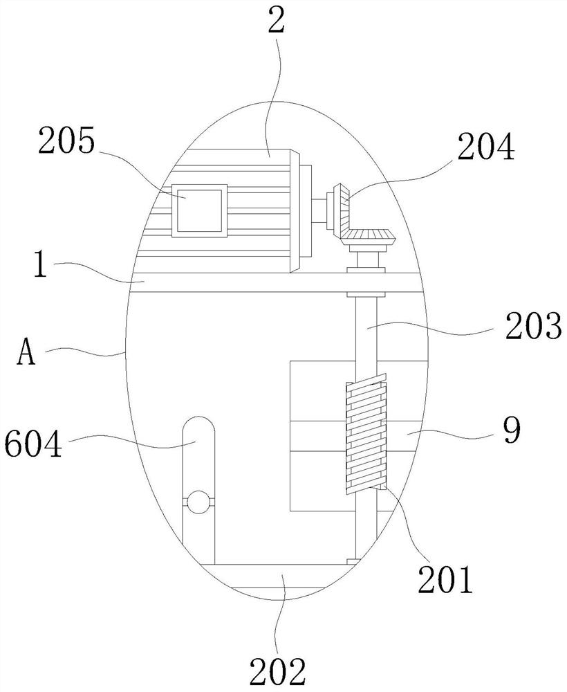
[0031] see Figure 1-8 , the present invention provides a technical solution: a waste recycling device for textile production, comprising a box 1, on which a driving mechanism 2, an absorbing mechanism 3, a processing mechanism 4, a rotating mechanism 5 and a cleaning mechanism are arranged. Recycling mechanism 6, connecting plate 8 and two groups of bearing plates 7 are welded on the outer surface of the bottom of box body 1, and a group of transmission rods ...


PUM


Abstract

The invention discloses a leftover material recycling device for textile production, and relates to the technical field of textiles. The leftover material recycling device for textile production comprises a box body, wherein a driving mechanism, an absorbing mechanism, a processing mechanism, a rotating mechanism and a sweeping and recycling mechanism are arranged on the box body; a connecting plate and two sets of bearing plates are welded and mounted on the outer surface of the bottom of the box body; a set of transmission rods are rotatably mounted on each of the two sets of bearing plates;one end of each transmission rod is rotatably mounted on the outer wall of the connecting plate; and a travelling wheel is welded and mounted at the other end of each transmission rod. The leftover material recycling device for textile production not only can recycle cotton fibers and silk threads floating in air and leftover materials such as rags and broken yarns accumulated on the ground in atextile workshop, but also can clean double surfaces of a textile penetrating through two sets of processing barrels, and recycles thread residues adhered to the textile into a collecting box, so thatthe using range and the using scene are expanded.

Description

technical field [0001] The invention relates to the technical field of textiles, in particular to a waste recovery device for textile production. Background technique [0002] The air in the textile production workshop is often filled with scraps such as cotton wool and silk threads, which will have a certain impact on the health of textile workers and the quality of textile production. Some scraps such as rags and broken yarns will also accumulate on the floor of the workshop. , affect the cleanliness of the environment, and the surface of the textile production and processing is easy to adhere to thread ends and dust particles, which need to be cleaned. However, most of the corner waste recovery devices on the market still have the problems of limited recovery range and poor effect. It is difficult to meet the requirements of the above situations at one time, the practicability is poor, and it is not conducive to promotion and use. In the process of air filtration in tradi...

Claims


Application Information

Patent Timeline
IPC IPC(8): B08B5/04B08B15/04B08B13/00A47L11/24A47L11/40
CPCA47L11/24A47L11/40A47L11/4013A47L11/4041A47L11/4069A47L11/4094B08B5/04B08B13/00B08B15/04
Inventor 张恒
Owner 青岛爱婴坊商贸有限责任公司
Learn More