Eureka AIR delivers breakthrough ideas for toughest innovation challenges, trusted by R&D personnel around the world.

Power grid current limiting device and system

A technology of current limiting device and power grid, which is applied in the electrical field, can solve the problems of current limiter failure, increased failure probability and risk, and many restricted conditions, so as to avoid damage and failure, avoid heat accumulation, and speed up heat dissipation efficiency. Effect

Active Publication Date: 2021-02-23
TAIYUAN LONGWAY ELECTRONICS SCI & TECH
View PDF7 Cites 0 Cited by
  • Summary
  • Abstract
  • Description
  • Claims
  • Application Information

AI Technical Summary

Problems solved by technology

Restricted by the insulation level, large-capacity high-speed switches are mostly used in 6-35kV high-voltage chambers. There are many operating links, many restrictions, and inconvenient installation and use. Moreover, due to the increased length of the connecting busbar, the failure probability and risk increase
[0004] The current limiter is a device used to limit the current. During the operation of the power grid, due to the large current of the power grid, in order to prevent short circuits, a current limiter will be installed in the line to reduce the current. However, the current limiter During the long-term use of the device, due to the large current passing through it for a long time, the internal components will generate heat for a long time under the influence of the current, and it is easy to be damaged, resulting in the failure of the current limiter and affecting the normal operation of the power grid.

Method used


Image

  • Power grid current limiting device and system
  • Power grid current limiting device and system
  • Power grid current limiting device and system

Examples


Embodiment 1

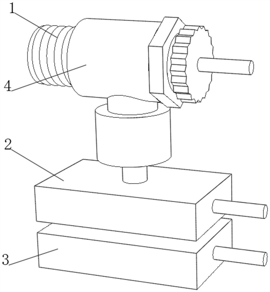
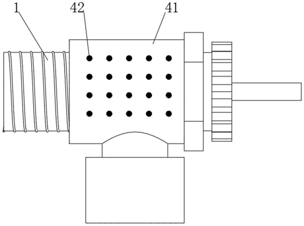
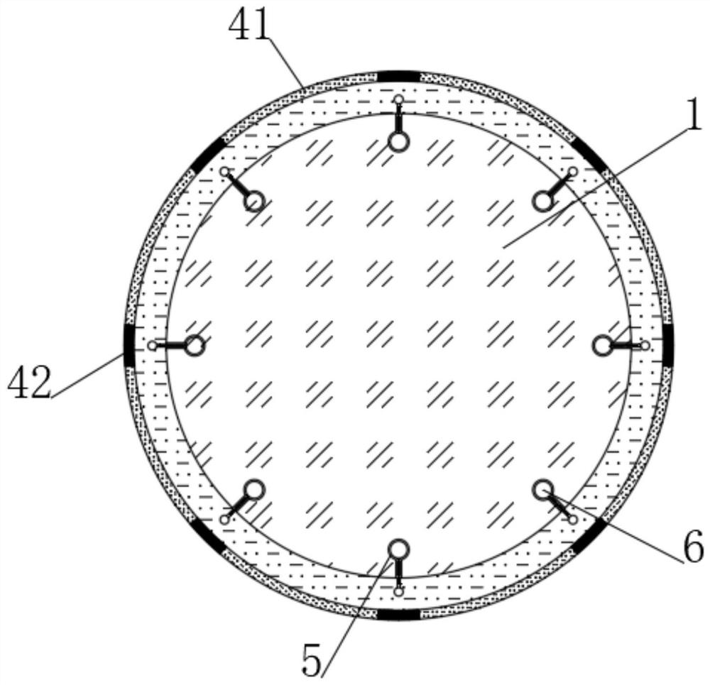
[0043] see Figure 1-3 , a current limiting device for a power grid, comprising a current limiting device body 1, an outer heat removal shell 4 is provided on a sealing sleeve at the outer end of the middle part of the current limiting device body 1, and a heat removal shell 4 is filled between the outer heat removal shell 4 and the current limiting device body 1 Liquid, the heat removal liquid can be heat conduction oil, and the outer heat removal shell 4 includes an outer radiator shell 41 and a plurality of inward heat collection fins 42 embedded in the outer radiator shell 41, and a plurality of heat conduction wires are embedded inside the inward heat collector fins 42 to conduct heat. One end of the wire runs through the inward heat collecting sheet 42 and is flush with the inner wall of the inward heat collecting sheet 42, and the other end of the heat conduction wire extends into the outer diffuser shell 41, and runs through the outer diffuser shell 41 to be flush with ...


PUM


Abstract

The invention discloses a power grid current limiting device and system, and belongs to the electrical field. By arranging an outer heat removal shell, during long-time work, a large amount of heat isgathered at an air lift transfer rod, so that an air lift ejector rod is heated to jack up the air lift transfer rod outwards, and the air lift ejector rod continuously moves out of an embedded heatgathering groove until the end part contacts with a corresponding inward heat accumulation sheet, on one hand, the contact area of the air lift transfer rod and a heat removal liquid is increased, outward dissipation of heat gathered on the air lift transfer rod is accelerated, and on the other hand, the heat on a heat transfer ball is directly transferred to the outside of an outer heat removal shell through a heat conduction wire, so that the heat dissipation efficiency is further improved; and when the heat on the heat transfer ball is reduced to a certain extent, the air lift transfer rodretracts into the embedded heat accumulation groove, the air lift transfer rod moves inwards and outwards again along with the re-accumulation of the heat, and the process is repeated continuously, sothat the heat dissipation efficiency is improved, the accumulation of the heat on the current limiting device body is effectively avoided, and the normal operation of a power grid is effectively guaranteed.

Description

technical field [0001] The invention relates to the electrical field, and more specifically, to a power grid current limiting device and system. Background technique [0002] Due to the development of the power grid, the maximum short-circuit current of the power grid in many areas exceeds the breaking capacity of the circuit breaker (currently the maximum is 63kA). Limited by this, a more effective short-circuit current breaking technology is required. [0003] In the early stage of domestic development, a large-capacity high-speed switch was developed that combined the explosive rapid breaking current-carrying bridge body, high-voltage current-limiting fuse, and high-energy-absorbing zinc oxide resistor. The large-capacity high-speed switch can be broken at the initial stage of short-circuit current rise. And limit its growth. When the short-circuit current reaches about 15% of the peak value, the short-circuit current can be cut off, and the action time is less than 1ms,...

Claims


Application Information

Patent Timeline
IPC IPC(8): H05K7/20
CPCH05K7/20445H05K7/20481H05K7/20218
Inventor 沙志成董霜刘威朱春萍郑帅王艳赵龙郑志杰张杰
Owner TAIYUAN LONGWAY ELECTRONICS SCI & TECH
Why Eureka
Eureka Blog
Learn More