
Mechanical-hydraulic combined extruder used for extrusion molding of plastic materials

An extrusion molding and mechanical hydraulic technology, applied in the field of mechanical hydraulic combined extruders, can solve problems such as affecting the yield of workpieces

Inactive Publication Date: 2021-02-19
陈伟敏
View PDF0 Cites 0 Cited by
  • Summary
  • Abstract
  • Description
  • Claims
  • Application Information

AI Technical Summary

Problems solved by technology

[0003] Based on the inventor's discovery above, the existing methods mainly have the following deficiencies, such as: when the equipment heat-melts the raw materials, it will open the hatches to the left and right sides to allow the hot melt to flow into the mould, and the plastic hot-melt also contains more Strong plasticity and adhesion, when the pouring work is completed and the hatch is about to be closed, part of the hot solution will adhere to the surface of the hatch, forming a pulling wire when the hatch is closed, affecting the yield of the workpiece

Method used


Image

  • Mechanical-hydraulic combined extruder used for extrusion molding of plastic materials
  • Mechanical-hydraulic combined extruder used for extrusion molding of plastic materials
  • Mechanical-hydraulic combined extruder used for extrusion molding of plastic materials

Examples


Embodiment 1

[0027] as attached figure 1 to attach Figure 5 Shown:

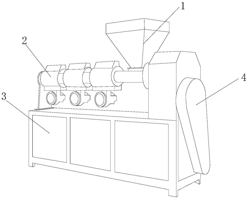
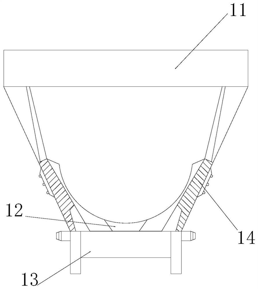
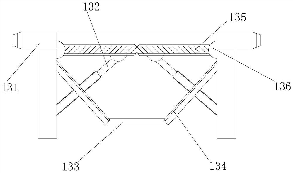
[0028] The invention provides a mechanical-hydraulic combined extruder for extrusion molding of plastic materials. Its structure includes a hot-melt mechanism 1, a plastic film block 2, an equipment seat 3, and a transmission shaft 4. The hot-melt mechanism 1 is embedded Installed directly above the equipment base 3, the plastic film block 2 is installed on the left side of the transmission shaft 4 by welding, and the right end surface of the equipment base 3 is embedded and connected with the transmission shaft 4, and the transmission shaft 4 is located on the heat The lower right side of the melting mechanism 1; the hot-melting mechanism 1 includes a material inlet 11, a material outlet 12, an intercepting mechanism 13, and a heating plate 14, and the described material inlet 11 is embedded and installed directly below the intercepting mechanism 13, The discharge port 12 is inlaid and mounted on the inner end surface...

Embodiment 2

[0035] as attached Image 6 to attach Figure 8 As shown: the closing mechanism 134 includes a movable block 41, a hollow hole 42, a rubber ring 43, a spring 44, a telescopic rod 45, and a roller 46. The hollow hole 42 is inlaid and mounted on the inner end surface of the movable block 41, the rubber ring 43 is inlaid and installed on the inner end surface of the closing mechanism 134, and the spring 44 is embedded and fixed around the outer end surface of the telescopic rod 45, so The telescoping rod 45 is embedded and installed on the inner end surface of the roller 46, and the roller 46 is symmetrically installed on the upper and lower ends of the right side of the rubber ring 43. The diameter of the inner ring of the rubber ring 43 is slightly larger than the distance between the upper and lower rollers 46. distance, the elastic cord 62 can be effectively clamped through the movable cooperation of the roller 46 and the spring 44 .

[0036] Wherein, the movable block 41 i...


PUM


Abstract

The invention discloses a mechanical-hydraulic combined extruder used for extrusion molding of plastic materials. The mechanical-hydraulic combined extruder structurally comprises a hot melting mechanism, a plastic film block, an equipment base and a transmission shaft. The hot melting mechanism is fixedly installed over the equipment base in an embedded manner, the plastic film block is installedon the left side of the transmission shaft in a welded manner, the end face of the right side of the equipment base is fixedly connected with the transmission shaft in an embedded manner, and the transmission shaft is located below the right side of the hot melting mechanism. An concentric shaft can be driven to rotate together while an intercepting plate swings, an elastic rope connected with amovable block in an embedded manner can pull embedded beads outwards, hollowed-out grooves connected with the embedded beads move outwards, the hollowed-out grooves in the upper end and the lower endare overlapped in the moving process, an empty groove is reserved to allow plastic solutions to flow so that the intercepting plate and a movable plate can be coaxial and cut off, and the situation that the yield is affected due to the fact that solutions are left in equipment excessively to form wiredrawing is avoided.

Description

technical field [0001] The invention belongs to the field of plastic processing machines, and more specifically relates to a mechanical-hydraulic combined extruder for extrusion molding of plastic materials. Background technique [0002] The mechanical-hydraulic combined extruder is a machine that plastically cools the plastic solution through the fixed mold and the hydraulic extrusion equipment. It mainly needs to pour the raw materials into the equipment, and heat the raw materials through the heating system in the equipment. Then it flows into the mold for plastic cooling. [0003] Based on the inventor's discovery above, the existing methods mainly have the following deficiencies, such as: when the equipment heat-melts the raw materials, it will open the hatches to the left and right sides to allow the hot melt to flow into the mould, and the plastic hot-melt also contains more Strong plasticity and adhesion, when the pouring work is completed and the hatch is about to ...

Claims


Application Information

Patent Timeline
Patent Type & Authority Applications(China)
IPC IPC(8): B29C48/27B29C48/25B29C48/793B29B13/02
CPCB29B13/022B29C48/25B29C48/27B29C48/793
Inventor 陈伟敏
Owner 陈伟敏
Learn More