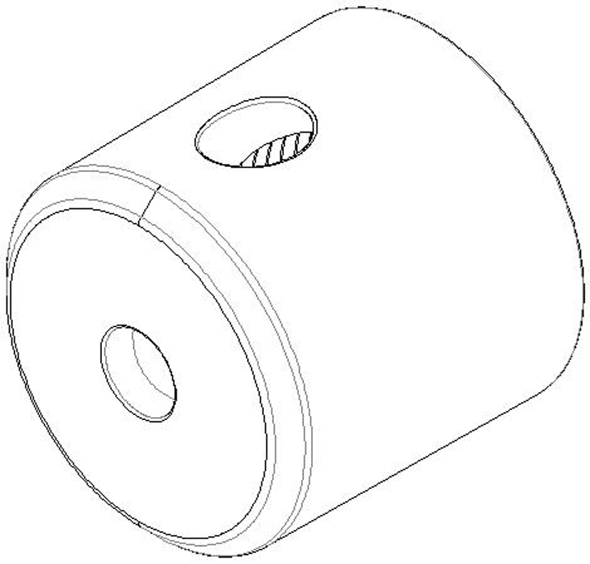
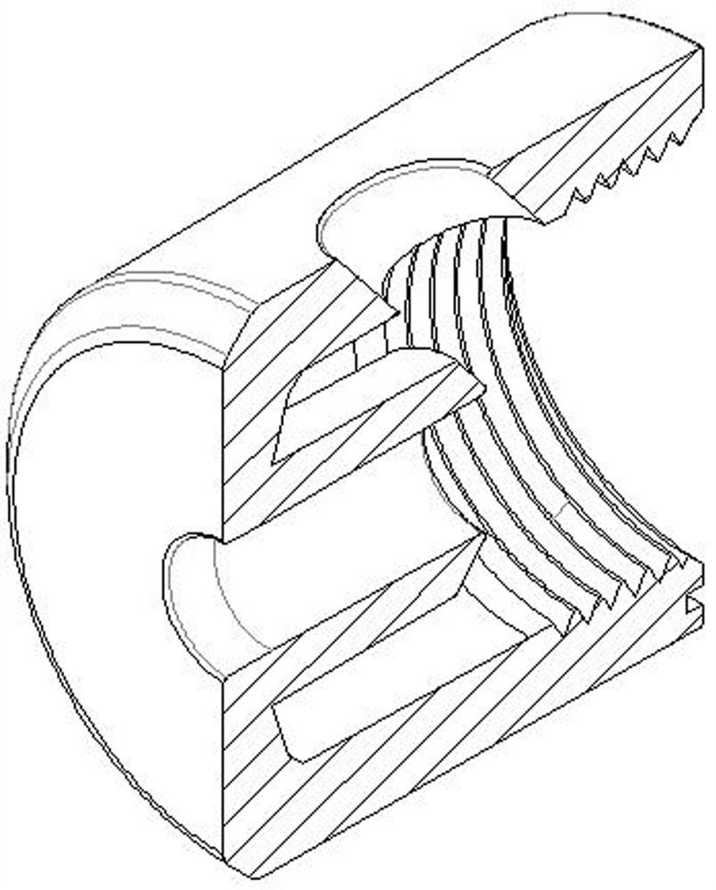
Mold for machining internal thread of plastic part and pulling core
A technology for internal threads and plastic parts, applied in the field of plastic molds, can solve the problems that the thread head and the thread tail cannot always be in the same position, the thread insert does not have a core limit structure, and the product does not meet the standard requirements. Improved demolding efficiency, reduced demolding time, and strong practicability
- Summary
- Abstract
- Description
- Claims
- Application Information
AI Technical Summary
Problems solved by technology
Method used
Image

Examples
Embodiment Construction
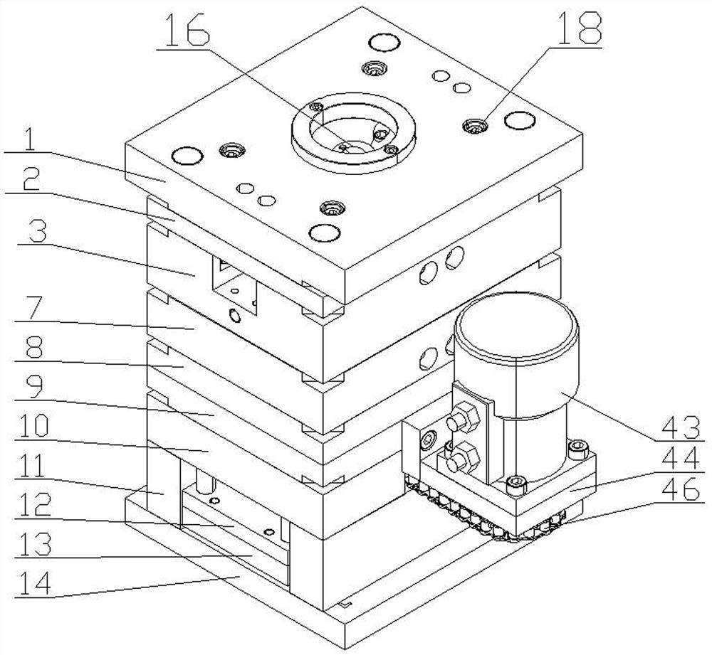
[0037]In order to facilitate those skilled in the art to better understand the present invention, the present invention will be described in further detail below with reference to the accompanying drawings and specific embodiments. The following are only exemplary and do not limit the protection scope of the present invention.
[0038] like Figure 3-7 As shown, the mold for processing the internal thread of plastic parts and the core-pulling mold described in this embodiment includes a fixed mold and a movable mold that are in the shape of a cuboid as a whole. A cylinder motor 43 is fixed on the movable mold. A first motor gear 45 is fixed on the output shaft. The end of the fixed mold close to the movable mold is provided with a cavity 4, the end of the movable mold close to the fixed mold is provided with a core 5 that matches the cavity, and the fixed mold is provided with a nozzle hole 16 and a flow channel 15. Specifically, the fixed mold includes a fixed mold fixing p...
PUM
 Abstract
Description
Claims
Application Information
 - R&D
- Intellectual Property
- Life Sciences
- Materials
- Tech Scout
- Unparalleled Data Quality
- Higher Quality Content
- 60% Fewer Hallucinations
Browse by: Latest US Patents, China's latest patents, Technical Efficacy Thesaurus, Application Domain, Technology Topic, Popular Technical Reports.
© 2025 PatSnap. All rights reserved.Legal|Privacy policy|Modern Slavery Act Transparency Statement|Sitemap|About US| Contact US: help@patsnap.com