
Device capable of guiding tool path to prevent tool collision and discharging sweeps during machining of CNC milling machine

A CNC milling machine and tool path technology, applied in the field of CNC milling machines, can solve the problems of safety accidents, tool deviation, wasting tools, etc., and achieve the effect of avoiding scrapping

Inactive Publication Date: 2021-02-12
宁波绵亘科技有限公司
View PDF0 Cites 1 Cited by
  • Summary
  • Abstract
  • Description
  • Claims
  • Application Information

AI Technical Summary

Problems solved by technology

[0002] In the machining of CNC milling machine, it is often easy for the tool to deviate or break and collide the moment the tool touches the workpiece. This will not only waste the tool but also cause the workpiece to be scrapped, which not only increases the cost virtually but also The occurrence of safety accidents affects the normal production of the CNC milling machine in the workshop, and the general CNC milling machine fixture is often not conducive to the discharge of waste chips. A device for guiding the anti-collision knife and waste chip discharge of a CNC milling machine processing tool path set forth in the present invention can solve the above problems

Method used


Image

  • Device capable of guiding tool path to prevent tool collision and discharging sweeps during machining of CNC milling machine
  • Device capable of guiding tool path to prevent tool collision and discharging sweeps during machining of CNC milling machine
  • Device capable of guiding tool path to prevent tool collision and discharging sweeps during machining of CNC milling machine

Examples


Embodiment Construction

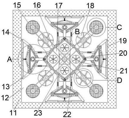
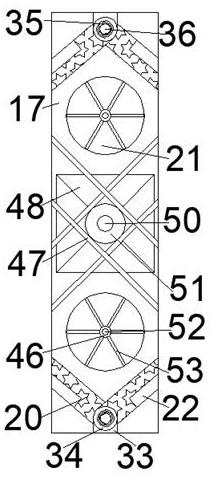
[0016] Combine below Figure 1-6 The present invention is described in detail, wherein, for the convenience of description, the orientations mentioned below are defined as follows: figure 1 The up, down, left, right, front and back directions of the projection relationship itself are the same.

[0017]A device for guiding anti-collision knives and waste discharge for CNC milling machine tool path according to the present invention includes a moving box 11, which is provided with a guiding cavity 12 with an opening forward and an intercepting spring 17 inside. The rear wall of the guide cavity 12 is provided with four moving holes 15 and guide chip discharge ports 18 that open backward. The arrangement is arranged symmetrically up, down, left, and right. The rear wall of the intercepting spring 17 is provided with four wind-powered chip discharge ports 21 with openings facing backward. Symmetrically distributed, the guide cavity 12 is fixedly connected with four fixed plates ...


PUM


Abstract

The invention discloses a device capable of guiding a tool path to prevent tool collision and discharging sweeps during machining of a CNC milling machine. The device comprises a moving box, a guide cavity with a forward opening and an intercepting spring are arranged in the moving box, and four moving holes with backward openings and a guide chip removal opening are formed in the rear wall of theguide cavity; and the four moving holes and the guide chip removal opening are distributed in an up-down and left-right symmetry mode with the center line of the guiding cavity as the symmetry center, and four wind power chip removal openings with backward openings are formed in the rear wall of the intercepting spring. The device can place a workblank or a workpiece in a clamp during machining of the CNC milling machine, when machining and feeding are carried out, the situation that when a tool makes contact with the workpiece, the tool collides or deviates can be prevented, tool breakage and workpiece scrapping are avoided, sweeps can be discharged in real time during machining and manufacturing, and the situation that machining and manufacturing are affected by the sweeps is avoided.

Description

technical field [0001] The invention relates to the related fields of numerical control milling machines, in particular to a device for guiding anti-collision knives and discharging waste chips in the processing tool path of numerical control milling machines. Background technique [0002] In the machining of CNC milling machine, it is often easy for the tool to deviate or break and collide the moment the tool touches the workpiece. This will not only waste the tool but also cause the workpiece to be scrapped, which not only increases the cost virtually but also The occurrence of safety accidents affects the normal production of the CNC milling machine in the workshop, and the general CNC milling machine fixture is often not conducive to the discharge of waste chips. A device for guiding the anti-collision knife and waste chip discharge of a CNC milling machine processing tool path set forth in the present invention can Solve the above problems. Contents of the invention ...

Claims


Application Information

Patent Timeline
Patent Type & Authority Applications(China)
IPC IPC(8): B23Q1/25B23Q15/00B23Q11/00
CPCB23Q1/25B23Q11/0042B23Q15/00
Inventor 白慧米
Owner 宁波绵亘科技有限公司
Learn More