
Rotary wire peeling and tin-soldering equipment and method

A rotary and wire technology, applied in the direction of line/collector parts, electrical components, circuits, etc., can solve the problems of soldering flexibility, limited application range, large space occupation, etc., to save working space and wide application range , well-arranged effect

Pending Publication Date: 2021-02-05
DONGGUAN JIALONG HAIJIE ELECTRONICS TECH CO LTD
View PDF0 Cites 2 Cited by
  • Summary
  • Abstract
  • Description
  • Claims
  • Application Information

AI Technical Summary

Problems solved by technology

However, the existing automatic wire stripping and welding device has a complex structure and takes up a lot of space. At the same time, the flexibility of soldering is affected and the scope of application is limited.

Method used


Image

  • Rotary wire peeling and tin-soldering equipment and method
  • Rotary wire peeling and tin-soldering equipment and method
  • Rotary wire peeling and tin-soldering equipment and method

Examples


Embodiment Construction

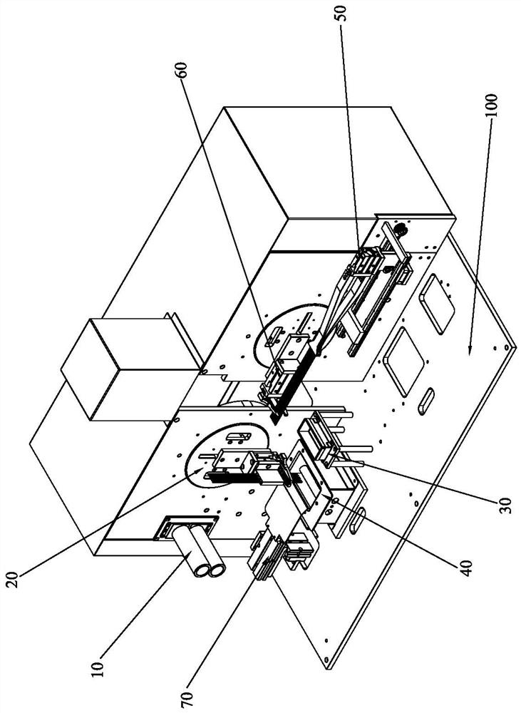
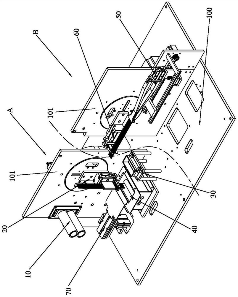
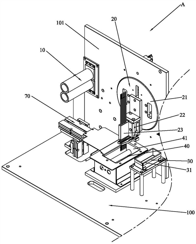
[0050] Please refer to Figure 1 to Figure 8 As shown, it shows the specific structure of the embodiment of the present invention.

[0051] A rotary wire peeling and soldering equipment, including a workbench 100 and a roller module 10 arranged on the workbench 100, a solder turntable module 20, a first flux tank module 30, a first tin furnace module 40, and a wire drawing module 50 , cutting module 60; Wherein:

[0052] The roller module 10 is used to smoothly feed the wire into the equipment, so that the soldering effect of the wire and the appearance quality of the wire can be improved;

[0053] The solder turntable module 20 has a turntable 21 and a first rotary driving device that drives the turntable 21 to rotate vertically around a horizontal axis. The device 22 is controlled by a lifting drive device to move up and down in the radial direction of the turntable 21; here, it can be detailed that: usually, the turntable 21 is provided with a ring gear (preferably arrang...


PUM


Abstract

The invention discloses rotary wire rod peeling and tin-soldering equipment and method. The rotary wire rod peeling and tin-soldering equipment comprises a tin soldering rotary disc module, a first tin soldering flux groove module, a first tin furnace module, a wire pulling module and a shearing module. The tin solderingrotary disc module is provided with arotary disc and a first rotary driving device for driving therotary disc to vertically rotate around a horizontal axis, and a first wire clamping device is arranged on therotary disc and can be controlled by a lifting driving device to moveup and down along the rotary disc; the wire pulling module is provided with a second wire clamping device and a wire pulling driving device for driving the second wire clamping device to move to pullthe wire; the shearing module is provided with a shearing device; and the second wire clamping device of the wire pulling module clamps one end of the wire to pull out the wire by a preset length, andthe shearing device peels and shears off the other end of the wire. Thus, through the design of the rotary wire rod peeling and tin-soldering equipment and the cooperative operation of all the modules, a series of operations of peeling, shearing, soldering flux sticking and tin soldering of the wire rod can be rapidly completed, and the machining efficiency is effectively improved.

Description

technical field [0001] The invention relates to the technical field of wire stripping and soldering equipment, in particular to a rotary wire stripping and soldering equipment and method, which are mainly but not limited to be used in the processing of winding wires of transformers. Background technique [0002] Existing transformers generally require a certain length of insulated wire to wind the secondary winding, and one end of the insulated wire needs to be glued with solder oil and soldered. At present, manual cutting of insulated wires and soldering is widely used. The efficiency of manual work is low, the labor cost is high, and the stability of processing quality is poor, which affects the processing yield. In addition, manual soldering will have a certain degree of safety. Hidden danger. [0003] Later, some automatic wire stripping and welding devices also appeared. Compared with manual operation methods, they have greatly improved in terms of production efficienc...

Claims


Application Information

Patent Timeline
Patent Type & Authority Applications(China)
IPC IPC(8): H01R43/02H01R43/28
CPCH01R43/02H01R43/28
Inventor 阮诗扬万睿周华平叶棣中王健
Owner DONGGUAN JIALONG HAIJIE ELECTRONICS TECH CO LTD
Learn More