A kind of sintering device and using method of sintered NdFeB magnet
A sintering device, NdFeB technology, applied in the direction of magnetic objects, magnetic materials, inductance/transformer/magnet manufacturing, etc., can solve the problem of non-gradual cooling of the furnace
- Summary
- Abstract
- Description
- Claims
- Application Information
AI Technical Summary
Problems solved by technology
Method used
Image
Examples
Embodiment 1
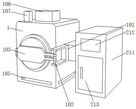
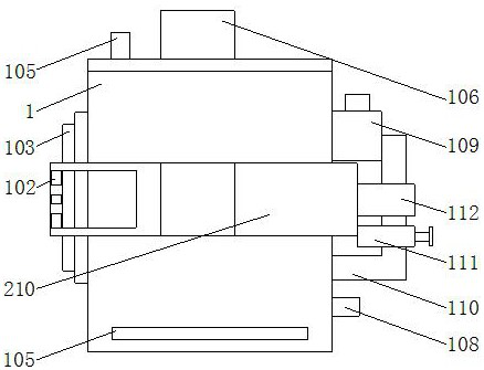
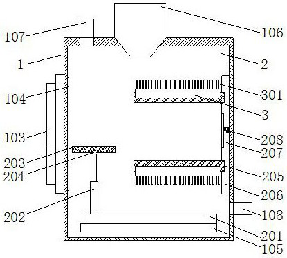
[0034] Such as Figure 1-Figure 8 As shown, the present invention provides a sintering device for sintering NdFeB magnets and a method for using the same, a furnace body 1 , a furnace chamber 2 and a water-cooled elbow 3 .
[0035] In this embodiment, the body of furnace 1 includes a hearth 2, a connection plate 206 is fixedly installed on one side of the interior of the hearth 2, a groove is provided on the front of the connection plate 206, and a lifting rod 209 is arranged inside the groove, and the lifting rod 209 Heating elements 205 are slidingly connected to the outer wall of the outer wall, and the number of heating elements 205 is two. One side surface of each heating element 205 is fixedly installed with a water-cooled elbow 3. Through exquisite design, the combination of water-cooled elbow 3 and heating element 205 Combined, it is convenient to carry out the first step of heat dissipation for the heating element 205 and the magnet above it, avoiding the problem of d...
Embodiment 2
[0039] Such as figure 1 As shown, on the basis of Embodiment 1, the present invention provides a technical solution: a fixed block 101 is fixedly installed on the right side surface of the furnace body 1, and a connecting rod 102 is fixedly connected to the inside of the fixed block 101, and the fixed block 101 is fixed by setting The connecting rod 102 of the connecting rod 102 is rotatably connected with a furnace cover 103, and the inside of the furnace cover 103 is provided with a sealing strip 104 to ensure the sealing of the inside of the furnace 2. The bottom of the furnace body 1 is provided with a cavity 105 to prevent the bottom of the furnace body 1 from being directly connected to the ground. Contact, the lower ground temperature affects the temperature at the bottom of the body of furnace 1, so that the bottom of the body of furnace can normally dissipate heat and keep warm. The back side of the fixed block 101 is fixedly connected with a control block 210, and the...
Embodiment 3
[0041] Such as Figure 1-2 As shown, on the basis of Embodiment 1 and Embodiment 2, the present invention provides a technical solution: preferably, a vacuum pump 106 is fixedly installed on the top of the furnace body 1, and an air inlet 107 is arranged on the left side of the vacuum pump 106, and the furnace The back of the furnace body 1 is fixedly connected with a circulating water pipe 110, and the back of the furnace body 1 is fixedly connected with an air outlet 108. An air valve is arranged inside the air inlet 107 and the air outlet 108. After local heat dissipation, the air inlet is controlled by the air valve. 107 and the gas flow of the gas outlet 108, further gradually cooling the inside of the furnace 2, a negative pressure water pump 111 is fixedly installed on the outer wall of the circulating water pipe 110, a condenser 112 is arranged above the negative pressure water pump 111, and the top side of the circulating water pipe 110 A water inlet tank 109 is fixed...
PUM
 Abstract
Description
Claims
Application Information
 - R&D Engineer
- R&D Manager
- IP Professional
- Industry Leading Data Capabilities
- Powerful AI technology
- Patent DNA Extraction
Browse by: Latest US Patents, China's latest patents, Technical Efficacy Thesaurus, Application Domain, Technology Topic, Popular Technical Reports.
© 2024 PatSnap. All rights reserved.Legal|Privacy policy|Modern Slavery Act Transparency Statement|Sitemap|About US| Contact US: help@patsnap.com


