
Artificial neuron calculation model construction method based on DNA cage structure

A neuron model and neuron computing technology, applied in the field of biological computing, can solve the problems of large number of DNA chains, cumbersome and complicated reaction process, leakage, etc., and achieve the effect of structural stability

Pending Publication Date: 2021-02-05
DALIAN UNIV
View PDF0 Cites 0 Cited by
  • Summary
  • Abstract
  • Description
  • Claims
  • Application Information

AI Technical Summary

Problems solved by technology

[0005] Although L.L. Qian et al. have realized the construction of the DNA neural network model, they are all based on the basic strand displacement reaction, and the number of DNA strands involved is extremely large, so it is cumbersome and complicated to realize all the reaction processes, and it is easy to cause leakage.

Method used


Image

  • Artificial neuron calculation model construction method based on DNA cage structure
  • Artificial neuron calculation model construction method based on DNA cage structure
  • Artificial neuron calculation model construction method based on DNA cage structure

Examples


Embodiment 1

[0049] Example 1: Normalization module

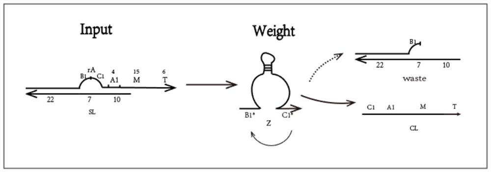
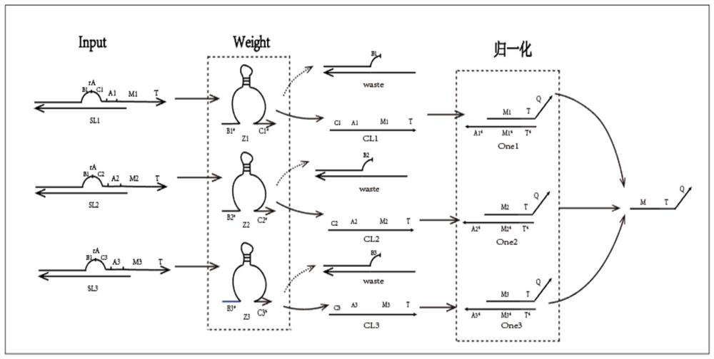
[0050] (1) Mix the rA-modified L1 chain (64 bases) with the small short chain S1 (39 bases) at a ratio of 1:1 in 1×TAE / Mg2+ buffer, and anneal from 90°C to At room temperature, a double-strand structure with rA-modified "bubbling" is formed, and the same is true for the other two double-strands SL2 and SL3; the normalization gates One1, One2, and One3 respectively divide the MTQ chain and the CL* chain at a ratio of 1:1. The ratio is mixed in 1×TAE / Mg2+ buffer and annealed from 90°C to room temperature to form a One gate complex;

[0051] (2) Put the input strands SL1, SL2, SL3, E6DNAzyme Z1, Z2, Z3 and each One gate into the same test tube with a concentration of 0.6uM, put them in an environment of 25°C, and react for about 12 hours;

[0052] (3) Figure 6 yes figure 2 The gel electrophoresis image of the corresponding product in (partial reaction image of the normalization module), lane 1 is the One1 gate, lane 3 is the CL1 chain...

Embodiment 2

[0053] Embodiment 2: threshold function module

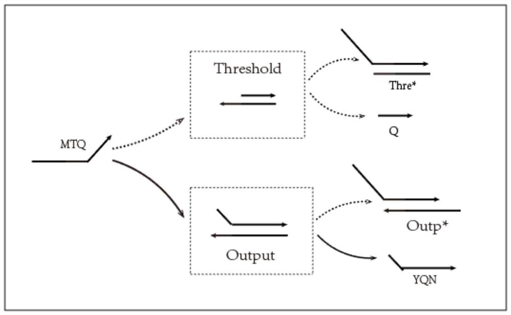
[0054] (1) Mix Q chain and Q*T*M_* chain in 1×TAE / Mg2+ buffer at a ratio of 1:1, and anneal from 90°C to room temperature to form Thre threshold gate complex; similarly, YQN chain and N*Q*T* chain are mixed in 1×TAE / Mg2+ buffer at a ratio of 1:1, and annealed from 90°C to room temperature to form an Outp gate complex;

[0055] (2) Place the MTQ chain and threshold gate Thre gate, MTQ chain and Outp gate in the ratio of 1:1 in test tube 4 and test tube 5 respectively, the concentration is 0.6uM; Put it in test tube 9 and test tube 10 according to the ratio of 1:1:1 and 2:1:1, the concentration is 0.6uM respectively, put it in the environment of 25 ℃, and react for about 12 hours;

[0056] (3) Figure 7 yes image 3 The gel electrophoresis figure of the corresponding product (partial reaction figure of the threshold function module), swimming lane 4 is the reaction lane of M1TQ and Thre, swimming lane 6 Thre* chain, swimming la...


PUM


Abstract

The invention discloses an artificial neuron calculation model construction method based on a DNA cage structure, and the method comprises the steps: constructing a cage structure with rA modification, enabling the cage structure to serve as an input layer of an artificial neuron model, and employing E6 DNAzyme as the weight of a neuron; constructing a normalization module, and using E6 DNAzyme Z1, Z2 and Z3 as weights of neurons; constructing a normalization module by utilizing an E6 DNAzyme enzyme digestion band rA modified cage structure, taking different outputs generated by enzyme digestion reaction as inputs of normalization reaction, and realizing a weighted sum process through normalization reaction; constructing a linear threshold processing module, namely a threshold function ofneurons, according to the reversible reaction of strand displacement and the reaction rate of strand displacement; and connecting the output module with the normalization module and the threshold processing module, so that normalized output is enabled to react with the Threshold gate preferentially; and then reacting with the Output gate after the reaction is finished; and finally, generating a real output, i.e., connecting each module to form an artificial neuron model.

Description

technical field [0001] The invention relates to the field of biological computing, in particular to a method for constructing an artificial neuron computing model based on a DNA cage structure. Background technique [0002] So far, DNA computing has made great progress in theory, design, and application, and has been deeply studied in many fields such as information processing, molecular intelligence, molecular encryption, and nanomachines. Most current biocomputing dynamic operations based on DNA molecules rely on the strand displacement reactions of DNA sequences in DNA networks. The calculation principle of DNA strand displacement is that DNA molecules will always migrate to the most stable state. In the reaction system, the most stable complementary DNA strands will be combined, and other DNA strands will be replaced. It has the advantages of fast response speed, high sensitivity, and high parallelism, and is therefore widely used in the research of DNA molecular logic ...

Claims


Application Information

Patent Timeline
Patent Type & Authority Applications(China)
IPC IPC(8): G16B5/00G06N3/06
CPCG16B5/00G06N3/061
Inventor 张强张立云王宾魏小鹏
Owner DALIAN UNIV
Learn More