A Method of Improving the Thermal Shock Resistance of Magnetic Cores
A technology of anti-thermal shock and magnetic core, which is applied in the manufacture of inductors/transformers/magnets, electrical components, circuits, etc., can solve the problems of poor resistance to welding thermal shock, poor performance of inductor products, strong thermal shock, etc. Effect of Thermal Shock Properties
- Summary
- Abstract
- Description
- Claims
- Application Information
AI Technical Summary
Problems solved by technology
Method used
Image

Examples
Embodiment 1
[0058] A method for improving the thermal shock resistance of a magnetic core, comprising the steps of:
[0059] 1) Preparation of glaze slurry: 5 parts by mass of borosilicate glass powder, 1 part by mass of CaO, 25 parts by mass of phenolic resin, 0.5 parts by mass of polyoxyethylene ether phosphate, 1 part by mass of polyamide wax , 0.5 parts by mass of polyether polyester modified organosiloxane, 0.5 parts by mass of polydimethylsiloxane and 66.5 parts by mass of ethanol are mixed into a corundum ball mill jar, and zirconium balls are added, ball milled for 10 hours, and passed through 300 mesh Sieve to obtain glaze slurry;
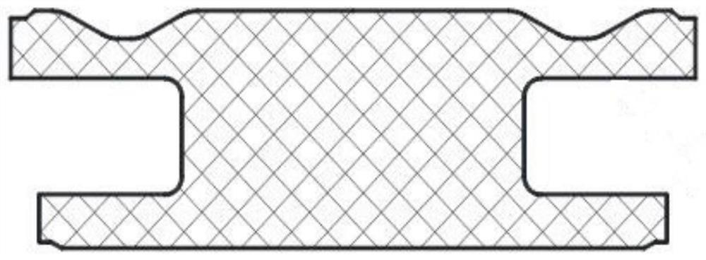
[0060] 2) Glazing: Spray the glaze slurry evenly on the magnetic core with a spray gun (the schematic diagram of the cross-section is shown in figure 1 shown) surface, then put the magnetic core into the mesh belt furnace and sinter at 850°C for 20min to form a glaze layer (thickness 2μm);
[0061] 3) Silvering: Coat both ends of the electrode surfa...
Embodiment 2
[0064] A method for improving the thermal shock resistance of a magnetic core, comprising the steps of:
[0065] 1) The borosilicate glass powder of 10 mass parts, the Al of 3 mass parts 2 o 3 , 25 parts by mass of polyvinyl butyral, 0.5 parts by mass of ammonium polyacrylate, 1 mass part of fumed silica, 0.5 parts by mass of acrylate leveling agent, 0.5 parts by mass of glyceryl oleate and 59.5 parts by mass Parts of ethanol was mixed into a corundum ball mill jar, and zirconium balls were added, ball milled for 10 hours, and passed through a 300-mesh sieve to obtain a glaze slurry;
[0066] 2) Glazing: Spray the glaze slurry evenly on the magnetic core with a spray gun (the schematic diagram of the cross-section is shown in figure 1 shown) surface, then put the magnetic core into the mesh belt furnace and sinter at 850°C for 20min to form a glaze layer (thickness 6μm);
[0067] 3) Silvering: Coat both ends of the electrode surface of the glazed magnetic core with silver p...
Embodiment 3
[0070] A method for improving the thermal shock resistance of a magnetic core, comprising the steps of:
[0071] 1) The borosilicate glass powder of 15 mass parts, the MnO of 5 mass parts 2 , the epoxy-modified acrylic resin of 25 mass parts, the ammonium polyacrylate of 0.5 mass part, the fumed silicon dioxide of 1 mass part, the acrylate leveling agent of 0.5 mass part, the olein glycerin of 0.5 mass part and 52.5 mass parts Parts of ethanol was mixed into a corundum ball mill jar, and zirconium balls were added, ball milled for 10 hours, and passed through a 300-mesh sieve to obtain a glaze slurry;
[0072] 2) Glazing: Spray the glaze slurry evenly on the magnetic core with a spray gun (the schematic diagram of the cross-section is shown in figure 1 shown) surface, then put the magnetic core into the mesh belt furnace and sinter at 850°C for 20min to form a glaze layer (thickness 10μm);
[0073] 3) Silvering: Coat both ends of the electrode surface of the glazed magnetic ...
PUM
| Property | Measurement | Unit |
|---|---|---|
| thickness | aaaaa | aaaaa |
| thickness | aaaaa | aaaaa |
| thickness | aaaaa | aaaaa |
Abstract
Description
Claims
Application Information
 - Generate Ideas
- Intellectual Property
- Life Sciences
- Materials
- Tech Scout
- Unparalleled Data Quality
- Higher Quality Content
- 60% Fewer Hallucinations
Browse by: Latest US Patents, China's latest patents, Technical Efficacy Thesaurus, Application Domain, Technology Topic, Popular Technical Reports.
© 2025 PatSnap. All rights reserved.Legal|Privacy policy|Modern Slavery Act Transparency Statement|Sitemap|About US| Contact US: help@patsnap.com