


Quick Research
Generate reliable direction feasibility study reports for your R&D in just a few steps.

Technical Q&A
Discover and master advanced knowledge NOW. Basics, ideas, possibilities, all at once.

Find Solutions
As an expert in R&D theories, this can generate solutions to your technical problems instantly.

Evaluate Feasibility
Analyze your overall solution with one click, know your potential R&D risks in advance.

Monitor Landscape
Get weekly tech updates, stay abreast of the latest tech innovations and key insights.
Production device of environment-friendly composite door plate
A technology for producing devices and door panels, which is applied in the directions of plywood presses, bonding of wooden veneers, and adhesive application devices, etc., which can solve the problem that the door panel pressing process is not explained too much.
- Summary
- Abstract
- Description
- Claims
- Application Information
AI Technical Summary
Problems solved by technology
Method used
Image

Examples
Embodiment 1
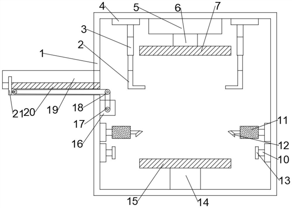
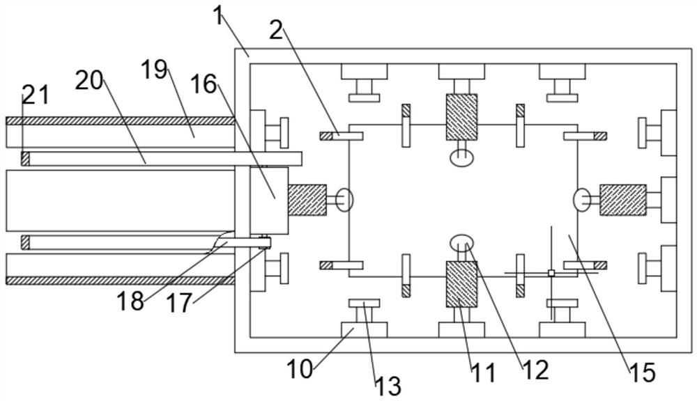
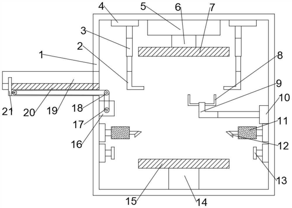
[0026] see figure 1 and 2 , in Embodiment 1 of the present invention, a production device for an environmentally friendly composite door panel includes a housing 1, a hydraulic cylinder 5, a pressure plate 7, a bottom plate 15, a handling claw 2, a positioning claw 8, a feeding platform 19, a draw bar 20, a motor 16. The positioning plate 13 and the plastic box 11; the pressure plate 7 is fixed to the hydraulic rod 6, and the hydraulic rod 6 is fixed to the hydraulic cylinder 5; the bottom plate 15 is fixed to the bottom surface of the housing 1 through the support seat 14, so The bottom plate 15 is located directly below the pressure plate 7; the plastic box 11 is fixed to one end of the electric push-pull rod, and the other end of the electric push-pull rod is fixed to the surface of the housing 1; the handling claw 2 is fixed to the electric telescopic rod 3 below, the electric telescopic rod 3 is fixedly connected to the track disk 4 on the top of the housing 1.
[0027]...
Embodiment 2
[0029] see Figure 1~3 , the main difference between this embodiment 2 and embodiment 1 is:
[0030] The telescopic head 9 is fixedly connected under the positioning claw 8 , and the telescopic head 9 is connected to the base 10 through the electric telescopic rod 3 , and the base 10 is fixedly connected to the inner side of the housing 1 .
[0031] When using this device, the staff place the cut boards on the feeding platform 19 according to the pressing sequence, the motor 16 drives the drawbar 20, drives the baffle 21 to pull the boards into the equipment, and the track disc 4 drives the transportation After the claw 2 fixes the position of the plate from all directions, the electric telescopic rod 3 extends downward to place the plate on the bottom plate 15, and then the track disc 4 drives the transport claw 2 to return to its original position, and continues to carry the plate. For the boards that need glue spraying on the surface, this equipment can drive the electric ...
PUM
 Abstract
Description
Claims
Application Information
 - R&D Engineer
- R&D Manager
- IP Professional
- Industry Leading Data Capabilities
- Powerful AI technology
- Patent DNA Extraction
Browse by: Latest US Patents, China's latest patents, Technical Efficacy Thesaurus, Application Domain, Technology Topic, Popular Technical Reports.
© 2024 PatSnap. All rights reserved.Legal|Privacy policy|Modern Slavery Act Transparency Statement|Sitemap|About US| Contact US: help@patsnap.com