
Vertical dry anaerobic system adopting bottom feeding and top discharging

A dry anaerobic and feeding technology, which is applied in the methods of sampling biological materials, sterilization methods, biochemical equipment and methods, etc., can solve the problems of high pressure in the tank, hindering the production of biogas from fermentation, and potential safety hazards. , to achieve the effect of preventing sedimentation and expanding the range of feed moisture content

Pending Publication Date: 2021-02-02
NORTH CHINA MUNICIPAL ENG DESIGN & RES INST
View PDF0 Cites 1 Cited by
  • Summary
  • Abstract
  • Description
  • Claims
  • Application Information

AI Technical Summary

Problems solved by technology

The scum layer hinders fermentation to produce biogas, causing excessive pressure in the tank and posing safety hazards
The sand layer blocks the pores and hinders the stable operation of the push flow in the tank
[0006] In summary, although the current existing technology can effectively deal with high-solid and easily degradable organic waste with high solid content and low miscellaneous content, the solid content of kitchen waste in my country is less than 25%, and the content of foreign matter is high. The problem of slag and sand settling needs to be improved, so a new anaerobic system suitable for the characteristics of kitchen waste in my country is needed to meet the needs of classified kitchen waste treatment projects

Method used


Image

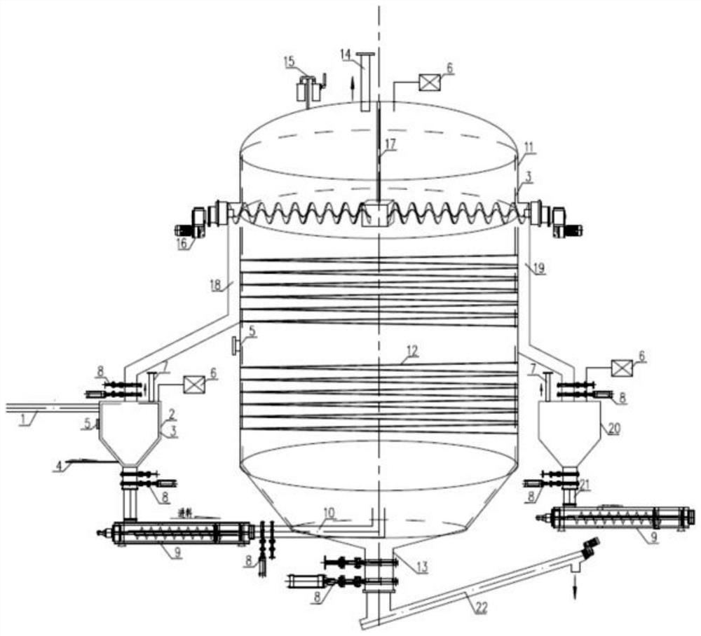
  • Vertical dry anaerobic system adopting bottom feeding and top discharging

Examples


Embodiment Construction

[0021] The present invention will be described in detail below in conjunction with the accompanying drawings and specific examples.

[0022] As shown in the figure, the present invention provides a vertical dry anaerobic system with bottom feed and top discharge, which is composed of feed reverse mixing tank 2 , anaerobic fermentation tank 11 , discharge tank 20 and sand discharge device 22 .

[0023] The upper part of the side wall of the feed reverse mixing tank 2 is connected to the raw material feed pipe 1, the bottom of the side wall is connected to the steam pipe 4 for heating the material in the tank, and the middle part of the side wall is provided with a temperature sensor 5. The bottom of the feed anti-mixing tank 2 is connected to the feed plunger pump 9 through a pipeline, and a double-knife gate valve 8 is installed on the pipeline, and an odor pipe 7 with a diameter of not less than DN50 and a radar level gauge are installed on the top of the feed anti-mixing tank...


PUM

PropertyMeasurementUnit
thicknessaaaaaaaaaa
thicknessaaaaaaaaaa

Abstract

The invention discloses a vertical dry anaerobic system adopting bottom feeding and top discharging. The vertical dry anaerobic system comprises a feeding back-mixing tank, an anaerobic fermentation tank, a discharging tank and a sand discharging device, wherein the upper part of the side wall of the feeding back-mixing tank is connected with a raw material feeding pipe, the bottom of the side wall is connected with a steam pipe, and the bottom end of the feeding back-mixing tank is connected with a feeding plunger pump; a heat insulation coil pipe is arranged outside a shell of the anaerobicfermentation tank, an anaerobic tank feeding pipe is arranged at the bottom of the shell, one end of the anaerobic tank feeding pipe is connected with the feeding plunger pump, the center of the bottom end of the shell is connected with a sand discharging pipe, and a plurality of spiral discharging machines are uniformly arranged at the upper part of the side wall of the shell and are respectivelyconnected with a material returning pipe and an anaerobic tank discharging pipe; the top of a shell of the discharging tank is connected with the anaerobic tank discharging pipe, the bottom of the shell is connected with a discharging pipe, and a discharging plunger pump is installed at the bottom of the discharging pipe; and the sand discharging device is connected with the bottom of the sand discharging pipe. The system can adapt to materials with 20-25% of solid content during feeding and dross in a layered mode during discharging, and the range of the water content of a feedstock in a vertical dry anaerobic fermentation technology is expanded.

Description

technical field [0001] The invention relates to the field of solid waste treatment, in particular to a vertical dry anaerobic system with bottom feeding and top discharging. Background technique [0002] At present, waste classification has become a new fashion, and it is the general trend to treat high-solid and easily degradable organic waste separately. At present, there are two types of dry anaerobic digestion technologies commonly used in my country: vertical and horizontal. Compared with the vertical anaerobic fermentation technology, the horizontal anaerobic fermentation technology occupies a larger area and has higher investment. The mature vertical dry anaerobic digestion technologies mainly include the Dranco process and the Valorga process. However, the existing vertical dry anaerobic digestion technologies are all derived from foreign countries. For the kitchen waste in my country, the content of light and heavy impurities is high, and the solid content is lowe...

Claims


Application Information

Patent Timeline
Patent Type & Authority Applications(China)
IPC IPC(8): C12M1/107C12M1/16C12M1/34C12M1/02C12M1/00
CPCC12M21/04C12M21/16C12M23/48C12M29/18C12M33/16C12M37/04C12M41/12C12M41/22C12M41/44C12M45/02C12M45/20
Inventor 郑苇李波陈子璇高波马换梅闵海华
Owner NORTH CHINA MUNICIPAL ENG DESIGN & RES INST
Learn More