Organic light-emitting device, and method for improving brightness uniformity

An electroluminescent device and luminescent technology, applied in the direction of electric solid-state devices, electrical components, semiconductor devices, etc., can solve the problems of different current and brightness of OLED panels, little effect, limited conductivity, etc., and achieve easy industrial production , reduce the impact, increase the effect of internal resistance

Pending Publication Date: 2021-01-29
GUAN YEOLIGHT TECH CO LTD
View PDF0 Cites 1 Cited by
  • Summary
  • Abstract
  • Description
  • Claims
  • Application Information

AI Technical Summary

Problems solved by technology

For example, the electrode material of an OLED light-emitting device has limited conductivity, and the electrodes are connected to external electrodes as limited contact points, and the contact points can only be distributed around the light-emitting device, and the voltage at the nearest contact point is different from the voltage at the farthest point. This will cause the current and brightness of each area of ​​the OLED panel to be different.
[0004] In the prior art, in order to improve the brightness uniformity of OLED light-emitting devices, it is generally carried out by improving the circuit design in the auxiliary electrode and the electrode layer, but these improved designs generally affect the appearance of the device, such as causing the grid of the screen to be patterned In this application, we break through the traditional lateral current control design method, because this method has great limitations in improving the brightness uniformity of the screen, and the effect is very small, which needs to be improved urgently

Method used


Image

  • Organic light-emitting device, and method for improving brightness uniformity
  • Organic light-emitting device, and method for improving brightness uniformity
  • Organic light-emitting device, and method for improving brightness uniformity

Examples


Embodiment 1

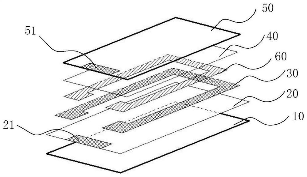
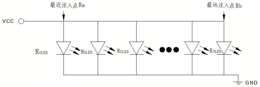
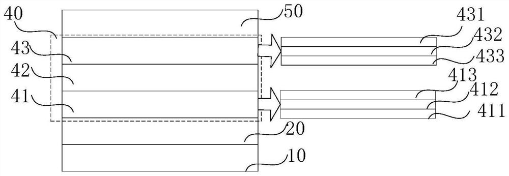
[0039] An embodiment of the present invention provides an organic electroluminescent device, figure 1 Shown is a schematic diagram of the layered structure of the organic electroluminescent device, figure 2 It is the principle diagram of the organic electroluminescence. Such as figure 1 and figure 2 As shown, the device includes a conductive substrate, the conductive substrate includes a substrate 10 and a first electrode layer 20 arranged on the substrate, the conductive substrate is divided into a light-emitting area and a non-light-emitting area; on the light-emitting area An organic functional layer 40 and a second electrode layer 50 are stacked, an auxiliary electrode 30 electrically connected to the first electrode 20 is arranged on the non-light-emitting area, an insulating layer 60 is also arranged on the auxiliary electrode 30, the first The electrode 20 and the second electrode 50 are used to access power. For organic electroluminescent screens, the uniformity ...

Embodiment 2

[0055] This embodiment also provides a method for improving the brightness uniformity of the organic electroluminescent device described in Embodiment 1. The method for improving brightness uniformity includes: adjusting the path resistance R of the auxiliary electrode a , The path resistance R from the injection point of the auxiliary electrode to the point farthest from the injection point in the light-emitting area b and the equivalent resistance R of the electroluminescent device OLED , so that it satisfies formula (1):

[0056]

[0057] To achieve the auxiliary electrode path resistance R a , The path resistance R from the injection point of the auxiliary electrode to the point farthest from the injection point in the light-emitting area b and the equivalent resistance R of the electroluminescent device OLED Satisfy formula (1), on the one hand, by improving R to a certain extent OLED The resistance value of the formula (1) can be satisfied to improve the brightne...

example 1

[0065] On the basis of Comparative Example 1, OLED devices 1-3 respectively use the LUMO energy level of the electron transport layer material ETL2 as -2.6eV, the LUMO energy level of the electron transport layer material ETL3 as -2.1eV, and the LUMO energy level of the electron transport layer material ETL4. The energy level is -1.6eV, because the internal resistance of the device is increased, so that the voltage and current of OLED device 1 are 6V and 20mA respectively; the voltage and current of OLED device 2 are 8V and 20mA respectively; the voltage and current of OLED device 3 are respectively 10V and 20mA.

[0066] The equivalent resistance R of OLED device 1 in this kind of lighting state OLED1 is 300 ohms, the current ratio of the two input points is calculated as 14.27%, and the calculation process is as follows:

[0067] (6 / (0.1+300)-6 / (50.05+300)) / (6 / (0.1+300))×100%=14.27%

[0068] By adopting the organic electroluminescence method of the embodiment of the presen...


PUM

PropertyMeasurementUnit
Mobilityaaaaaaaaaa
Thicknessaaaaaaaaaa
Thicknessaaaaaaaaaa

Abstract

The invention provides an organic light-emitting device, and a method for improving brightness uniformity. The device and the method are used for solving the problem of non-uniform brightness of an OLED light-emitting device in the prior art. The device is composed of a light-emitting region and a non-light-emitting region, the light-emitting region comprises a substrate, a first electrode, a functional layer and a second electrode, and the first electrode, the functional layer and the second electrode are sequentially arranged on the substrate in a layered mode, and the first electrode and the second electrode are used for being connected with a power source. The non-light-emitting region comprises an auxiliary electrode which is arranged between the first electrode and the functional layer and electrically connected with the first electrode, and the path resistance Ra of the auxiliary electrode, the path resistance Rb from the injection point of the auxiliary electrode to the point,farthest away from the injection point, of the light-emitting region and the equivalent resistance ROLED of the electroluminescent device meet a preset relational expression. By designing a longitudinal resistor and combining a transverse path resistor for proportional adjustment, the brightness uniformity of a screen is improved, the process is simple, and industrial production is easy to realize.

Description

technical field [0001] The invention specifically discloses an organic electroluminescent device and a method for improving brightness uniformity, belonging to the field of lighting equipment. Background technique [0002] As lighting devices, traditional fluorescent lamps and incandescent lamps have certain defects. Although incandescent lamps have a high color rendering index, their energy efficiency is low; while fluorescent lamps have high energy efficiency, but their color rendering index is low and mercury pollution exists. The light-emitting diode (Light-Emitting Diode, LED) lighting device commonly used now is made of inorganic light-emitting materials, has the highest luminous efficiency in the red wavelength range, and the luminous efficiency decreases toward the green wavelength range with the highest luminous factor of red. Small. When white light is emitted by combining red light-emitting diodes, green light-emitting diodes and blue light-emitting diodes, the l...

Claims


Application Information

Patent Timeline
IPC IPC(8): H01L51/52
CPCH10K50/814H10K50/824Y02E10/549
Inventor 于倩倩鲁天星胡永岚
Owner GUAN YEOLIGHT TECH CO LTD
Why Eureka
Try Eureka