
Multifunctional full-automatic rotary material taking and feeding mechanism

A fully automatic technology for retrieving and feeding materials, which is applied in the field of multi-functional automatic rotary retrieving and feeding mechanisms, can solve the problems of increasing manufacturing costs and maintenance costs, unfavorable enterprises to expand scale, and low processing accuracy, so as to reduce manufacturing costs and maintenance Cost, beneficial to the scale of the enterprise, and the effect of improving the processing accuracy

Pending Publication Date: 2021-01-29
翁宗享
View PDF9 Cites 6 Cited by
  • Summary
  • Abstract
  • Description
  • Claims
  • Application Information

AI Technical Summary

Problems solved by technology

[0003] The purpose of the present invention is to solve the problems existing in the prior art that independent systems and power sources are used to individually control each operation process, which not only requires cumbersome operation, but also consumes a lot of energy, and greatly increases manufacturing costs and maintenance costs, which is not conducive to enterprises. Due to the shortcomings of expanding the scale and low processing accuracy, a multi-functional fully automatic rotary retrieving and feeding mechanism is proposed.

Method used


Image

  • Multifunctional full-automatic rotary material taking and feeding mechanism
  • Multifunctional full-automatic rotary material taking and feeding mechanism
  • Multifunctional full-automatic rotary material taking and feeding mechanism

Examples


Embodiment 1

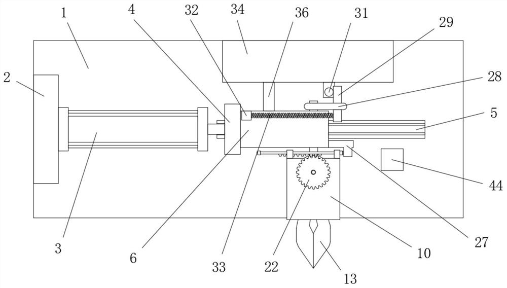
[0038] refer to Figure 1-12 , a multi-functional fully automatic rotary retrieving and feeding mechanism, including a base 1, the top of the base 1 is provided with a slide rail 5, the top side of the base 1 is fixedly connected with a mounting plate 2, and the side of the mounting plate 2 is close to the slide rail 5 A telescopic cylinder 3 is fixedly installed, and an L-shaped slide plate 4 is fixedly connected to the horizontal output shaft of the telescopic cylinder 3, and the bottom of the L-shaped slide plate 4 is slidably connected with the slide rail 5, and the side of the L-shaped slide plate 4 away from the telescopic cylinder 3 is provided There is a chute 43, a sliding seat 6 is slidably connected in the chute 43, one side of the sliding seat 6 extends to the outside of the L-shaped slide plate 4 and is rotatably connected with a rotating block 10, and the rotating block 10 is a hollow structure, and the rotating block 10 is away from One side of the sliding seat ...

Embodiment 2

[0040] Further improved on the basis of embodiment one:

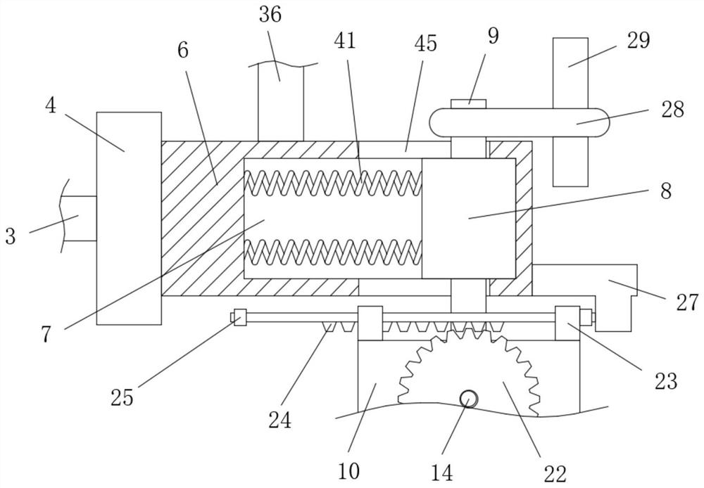
[0041] In the present invention, the inside of the sliding seat 6 is provided with a sliding chamber 7, and two sliding holes 45 are symmetrically provided on the side of the sliding seat 6 away from each other. The sliding chamber 7 is slidably connected with a slider 8. The side runs through and is connected with the first rotating rod 9, and one end of the first rotating rod 9 passes through the corresponding sliding hole 45 and is fixedly connected with the outer wall of the side of the rotating block 10 close to the sliding seat 6, and the other end of the first rotating rod 9 passes through the other side. A sliding hole 45 is connected with the transmission assembly, one side of the sliding block 8 is in contact with the inner wall of the side of the sliding chamber 7 away from the L-shaped slide plate 4, and the other side of the sliding block 8 is symmetrically fixedly connected with two second pullers. Stretch...


PUM


Abstract

The invention belongs to the technical field of machining, and particularly relates to a multifunctional full-automatic rotary material taking and feeding mechanism. For the problems that in the priorart, the operation is tedious, the energy consumption is high, the manufacturing cost and the maintenance cost are greatly increased, the expansion of the scale of an enterprise is not facilitated, and meanwhile, the machining precision is not high due to the fact that an independent system and an independent power source are adopted for independently controlling each operation procedure, now thescheme is proposed as follows: the multifunctional full-automatic rotary material taking and feeding mechanism comprises a base, wherein a sliding rail is arranged at the top of the base; a mountingplate is fixedly connected to one side of the top of the base; and a telescopic cylinder is fixedly mounted at one side, close to the sliding rail, of the mounting plate. The clamping, material taking, feeding and rotating operation procedures can be achieved at the same time through one cylinder, so that an operation system is simplified, the operation mode is simple, the energy consumption is low, the manufacturing cost and the maintenance cost are greatly reduced, the expansion of the scale of the enterprise is facilitated, meanwhile, the machining precision is improved, and the developmentprospect is wide.

Description

technical field [0001] The invention relates to the technical field of mechanical processing, in particular to a multi-functional fully automatic rotary retrieving and feeding mechanism. Background technique [0002] With the development of science and technology, the demand for intelligence is increasing day by day, and some simple mechanical operations can no longer meet the daily production. At present, in the process of processing the automobile shaft, it is often necessary to rotate it by 90 degrees for feeding in order to carry out the next process. The operation process, the traditional manual rotation is time-consuming and laborious, the work efficiency is low, and the rotation is also realized by mechanical movement. However, the traditional mechanical operation uses an independent system and power source for each shaft to clamp, feed, rotate, and displace. Each operation process is controlled separately, which is not only cumbersome to operate, but also consumes a ...

Claims


Application Information

Patent Timeline
Patent Type & Authority Applications(China)
IPC IPC(8): B65G47/82B65G47/90
CPCB65G47/82B65G47/90
Inventor 翁宗享
Owner 翁宗享
Learn More