
Double-ring oil-immersed power transformer with 1000kV high-voltage winding split

A technology for power transformers and high-voltage windings, which is applied to transformer handling devices, transformer/inductor cooling, transformer/inductor magnetic cores, etc. It can solve problems such as high transportation costs, large voltage differences, and high insulation levels of high-voltage windings. Difficulties in insulation technology, reducing the insulation level of switches, and reducing the effect of transportation height

Pending Publication Date: 2021-01-22
CHANGZHOU TOSHIBA TRANSFORMER
View PDF0 Cites 0 Cited by
  • Summary
  • Abstract
  • Description
  • Claims
  • Application Information

AI Technical Summary

Problems solved by technology

The advantage of the winding arrangement structure of the existing 1000kV double-turn transformer is that the insulation structure is simple and the design is convenient; the disadvantage is that due to the high insulation level of the high-voltage winding, the voltage difference between the head and the end of a single high-voltage winding is large. It will be designed to be very high, so that the overall transportation height of the transformer is very high, making it very difficult to transport the existing 1000kV double-turn transformer from the manufacturer to the power plant (by setting it in a remote area or mountainous area rich in natural resources). Risky and expensive to ship

Method used


Image

  • Double-ring oil-immersed power transformer with 1000kV high-voltage winding split
  • Double-ring oil-immersed power transformer with 1000kV high-voltage winding split
  • Double-ring oil-immersed power transformer with 1000kV high-voltage winding split

Examples


Embodiment 1)

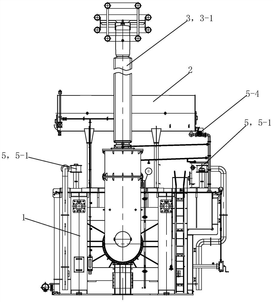
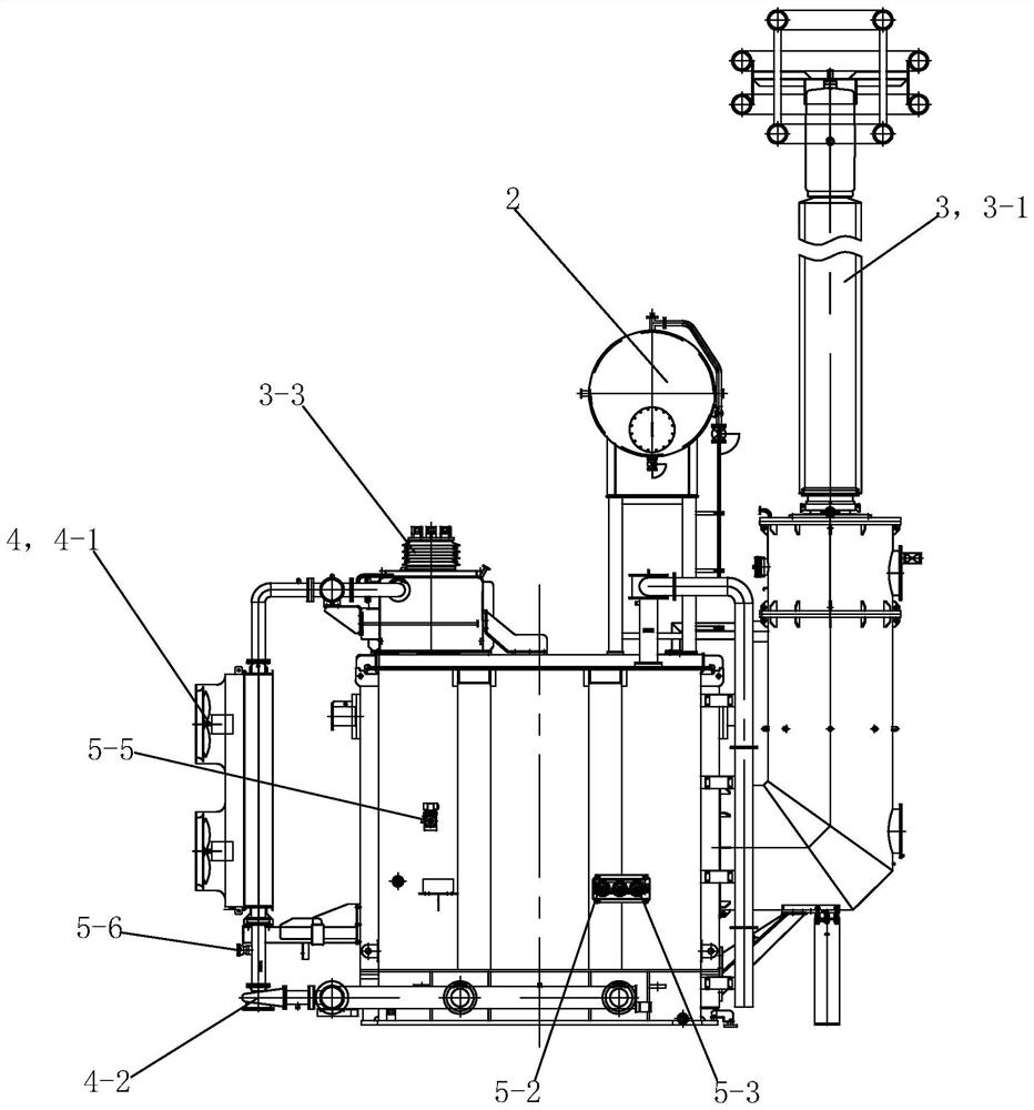
[0036] See Figure 1 to Figure 7, the 1000kV high-voltage winding split double-turn oil-immersed power transformer of this embodiment is mainly composed of an oil tank 1, an oil conservator 2, a bushing 3, a cooling device 4, a secondary protection device 5, an off-excitation tap changer 6, Composed of iron core 7, winding assembly 8 and lead wire 9.

[0037] The oil storage tank 2 is located above the oil tank 1, and the oil storage tank 2 is used to store transformer oil; the oil storage tank 2 communicates with the internal oil circuit of the oil tank 1, and the oil tank 1 is filled with transformer oil. The above is the prior art and will not be described in detail . In order to reduce the magnetic flux leakage of the fuel tank 1 and reduce the stray loss of the fuel tank 1, a magnetic shield 1-1 is provided on the inner surface of the fuel tank 1. In order to enhance the insulation effect of the fuel tank 1, a graphite shielding layer is also provided outside the magneti...


PUM


Abstract

The invention provides a double-ring oil-immersed power transformer with 1000kV high-voltage winding split. The double-ring oil-immersed power transformer comprises an oil tank, an oil storage cabinet, a sleeve, cooling equipment, secondary protection equipment, a non-excitation voltage regulating switch, an iron core, a winding assembly and a lead. The winding assembly comprises a voltage regulating winding, a first high-voltage winding, a first low-voltage winding, a second low-voltage winding and a second high-voltage winding which are sequentially arranged from inside to outside; the voltage regulating winding is close to an iron core main column, and insulating cylinders and supporting strips are arranged between the voltage regulating winding and the iron core main column, between the adjacent windings and between the second high-voltage winding and an iron core side column. The voltage regulating winding is connected in series with the first and second high-voltage windings to form a high-voltage winding part of the transformer; the first and second low-voltage windings are connected in series to form a low-voltage winding part of the transformer. Through the overall structural design, the problem that in the prior art, a 1000kV double-ring oil-immersed power transformer is high in transportation height is effectively solved, and the switch is low in insulation level, loss, noise and temperature rise and high in insulation reliability.

Description

technical field [0001] The invention relates to the technical field of ultra-high voltage transformers, in particular to a double-turn oil-immersed power transformer with split 1000kV high-voltage windings. Background technique [0002] 1000kV UHV transmission has obvious advantages in long-distance, large-capacity, low-loss power transmission and saving land resources. It has developed rapidly in recent years. The 1000kV double-turn transformer is an important equipment for UHV power transmission. On the side of the power plant, it can raise the low voltage to 1000kV for long-distance power transmission. At present, the windings of the common 1000kV double-turn transformer include the first low-voltage winding, the second low-voltage winding, the high-voltage winding and the voltage regulating winding. The voltage regulating winding is placed in the high voltage winding, and the first low voltage winding and the second low voltage winding form a U-shaped structure. The ad...

Claims


Application Information

Patent Timeline
Patent Type & Authority Applications(China)
IPC IPC(8): H01F27/00H01F27/12H01F27/14H01F27/24H01F27/28H01F27/30H01F27/32H01F27/34H01F27/36H01F27/40
CPCH01F27/002H01F27/28H01F27/40H01F27/324H01F27/30H01F27/2828H01F27/36H01F27/24H01F27/14H01F27/12H01F27/341H01F27/2876
Inventor 洪剑平周焕薛晖蔡琦峰李绍成
Owner CHANGZHOU TOSHIBA TRANSFORMER
Learn More