Fast imaging method and device based on neural network positioning algorithm
A neural network and localization algorithm technology, applied in the field of fast imaging methods and devices based on neural network localization algorithm, can solve the problems of high electronic noise and increase of reconstruction time, etc.
- Summary
- Abstract
- Description
- Claims
- Application Information
AI Technical Summary
Problems solved by technology
Method used
Image

Examples
Embodiment 1
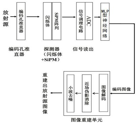
[0075] Embodiment 1: see Figure 1 to Figure 6 , a fast imaging method based on a neural network positioning algorithm, applied to a fast imaging device based on a neural network positioning algorithm, the device includes a coded aperture collimator, a detector and a signal readout unit connected in sequence, the detector Including the scintillator, the rays act on the surface of the scintillator through the coded hole collimator, the detector is converted into a pulse signal array, and then converted into a detector array response matrix through a signal readout unit, and the method includes the following steps:
[0076] (1) Determine the size of the coded hole collimator and detector according to the detection range, establish a coordinate system on the surface of the scintillator, and divide the surface of the scintillator into several grids, each grid corresponds to a coordinate;
[0077] (2) Train an MLP neural network to obtain a network model, specifically:
[0078] (2...
Embodiment 2
[0110] Example 2: see Figure 1 to Figure 6 , in this embodiment, we need to detect and quickly image the pollution in the lungs of adults. In this embodiment, we first establish a fast imaging device based on the neural network positioning algorithm, and its structure is the same as the one in embodiment 1. Fast imaging device based on neural network localization algorithm. The specific imaging method applied to the device includes the following steps:
[0111] (1) Determine the size of the coded hole collimator and detector according to the detection range, and establish a fast imaging device based on the neural network positioning algorithm, which can be realized through steps (11)-(18);
[0112] (11) We preset the square range covering the entire lung as the imaging range, and the size is FoV =300 mm ×300 mm ;
[0113] (12) Select the detector as a monolithic LaBr3 detector with a thickness of side length d d =301 mm , the detection range is 301 mm ×301 mm...
Embodiment 3
[0139] Embodiment 3: see Figure 6-Figure 9c , based on Example 2, Figure 7a , 7b , 7c are three diagrams of radioactive sources. In this implementation, we have selected three radioactive sources of different shapes, which are Figure 7a : point radioactive source; Figure 7b : circular radioactive source; Figure 7c , a radioactive source of irregular shape. And for better illustration effect, Figure 7c In , we use the pattern of the letter "CDUT" to demonstrate, in fact, it is not limited to this pattern.
[0140] we take Figure 7b Taking the radioactive source as an example, the radioactive source passes through the code hole collimator, the crystal, and the neural network to obtain the coded image of the radioactive source, such as Figure 8a As shown in the figure on the left, it is extended and filled with zeros around it, such as Figure 8a As shown on the right; Figure 8b It is to process the matrix function of the MPA-MURA coded aperture collimator;
[...
PUM
 Abstract
Description
Claims
Application Information
 - R&D
- Intellectual Property
- Life Sciences
- Materials
- Tech Scout
- Unparalleled Data Quality
- Higher Quality Content
- 60% Fewer Hallucinations
Browse by: Latest US Patents, China's latest patents, Technical Efficacy Thesaurus, Application Domain, Technology Topic, Popular Technical Reports.
© 2025 PatSnap. All rights reserved.Legal|Privacy policy|Modern Slavery Act Transparency Statement|Sitemap|About US| Contact US: help@patsnap.com