Message delay processing method and system
A delay processing and message technology, applied in the computer field, can solve problems such as low data transmission efficiency, and achieve the effect of avoiding subsequent delay problems
- Summary
- Abstract
- Description
- Claims
- Application Information
AI Technical Summary
Problems solved by technology
Method used
Image
Examples
Embodiment 1
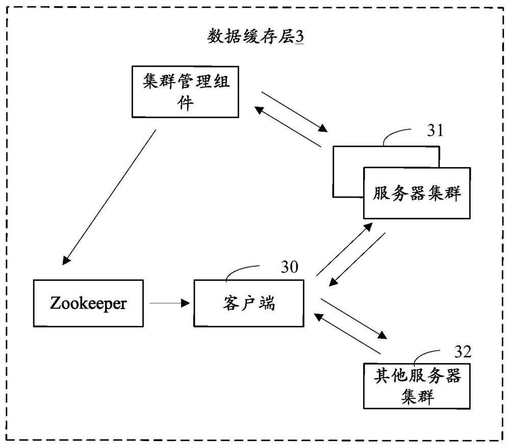
[0051]figure 2 It schematically shows the operating environment diagram of the message delay processing method of the present application, which may have the following combination parts:
[0052]The client 30 is an application program running in the server, and is used to send the message in the data source 1 to the server cluster. The message delay processing method may be a part of the client 30 or a plug-in in the form of code. It can be seen that the execution subject of the message delay processing method described in this embodiment is the device running the client 30.
[0053]The server cluster 31, such as a Kafka cluster, is used to store messages.
[0054]The other server cluster 32 is a cluster different from the server cluster 31 and may be a standby cluster of the server cluster 31.
[0055]Cluster management components, such as Kafka guradian, can collect operating information of server clusters.
[0056]Distributed service coordination components, such as Zookeeper, are used for serv...
Embodiment 2
[0074]Figure 4 It schematically shows a flowchart of a message processing method according to the second embodiment of the present application.
[0075]Such asFigure 4 As shown, the message delay processing method may include steps S400 to S404, where:
[0076]Step S400: Send multiple messages to multiple partitions in the server cluster.
[0077]The client 30 can send each message to one of the partitions under the corresponding Topic according to the attributes, identifiers, etc. of each message. The multiple messages may be sent to one or more partitions in the server cluster 31.
[0078]When the client 30 sends the multiple messages, it may be sent one by one or batch by batch. Taking the client 30 sending messages to partition A in batches as an example, the client 30 sends 1000 messages to partition A in batches.
[0079]Step S402: Obtain the message sending status of the server cluster in the current time window based on a time sliding window, where the message sending status includes the r...
Embodiment 3
[0129]Picture 11 Shows a block diagram of a message delay processing system according to the third embodiment of the present application. The message delay processing system can be divided into one or more program modules, one or more program modules are stored in a storage medium, and Executed by one or more processors to complete the embodiments of the present application. The program module referred to in the embodiment of the present application refers to a series of computer program instruction segments capable of completing specific functions. The following description will specifically introduce the function of each program module in this embodiment. Such asPicture 11 As shown, the message delay processing system 1100 may include the following components:
[0130]The sending module 1110 is used to send multiple messages to multiple partitions in the server cluster;
[0131]The obtaining module 1120 is configured to obtain the message sending status of the server cluster, where the ...
PUM
 Abstract
Description
Claims
Application Information
 - Generate Ideas
- Intellectual Property
- Life Sciences
- Materials
- Tech Scout
- Unparalleled Data Quality
- Higher Quality Content
- 60% Fewer Hallucinations
Browse by: Latest US Patents, China's latest patents, Technical Efficacy Thesaurus, Application Domain, Technology Topic, Popular Technical Reports.
© 2025 PatSnap. All rights reserved.Legal|Privacy policy|Modern Slavery Act Transparency Statement|Sitemap|About US| Contact US: help@patsnap.com


