
Control valve for a variable capacity compressor and method for manufacturing same

a variable capacity compressor and control valve technology, which is applied in the direction of machines/engines, flexible member pumps, positive displacement liquid engines, etc., can solve the problems of difficult to fix non-magnetic materials, difficult to obtain a quick cooling performance, and difficulty in obtaining explosion or noise caused by explosion, etc., to improve the operability of the variable capacity compressor in an initial operating stage, improve the performance and delay in the operation of the variable capacity compressor

Active Publication Date: 2014-09-04
DOOWON TECHN COLLEGE +1
View PDF4 Cites 14 Cited by
  • Summary
  • Abstract
  • Description
  • Claims
  • Application Information

AI Technical Summary

Benefits of technology

This patent is about a control valve for a variable capacity compressor and a method of manufacturing it. The control valve can prevent delays in the operation of the compressor and make it easier to start up even if it has not been used for a long time. This improves the performance of the compressor. The method of manufacturing the control valve is also easier and more efficient, which leads to better productivity.

Problems solved by technology

However, when a conventional variable capacity compressor is initially operated after being neglected for a certain period of time, specifically in summer, a pressure in a suction chamber is increased or a pressure in a crank chamber is increased by a liquid refrigerant, thereby delaying an operation of the conventional variable capacity compressor, and thus it is difficult to obtain a quick cooling performance.
In addition, an explosion or noise caused by the explosion may be generated when the conventional variable capacity compressor is operated.
At this time, it may be difficult to fix the non-magnetic material and fixability of the non-magnetic material may not be satisfactory in the conventional control valve.

Method used


Image

  • Control valve for a variable capacity compressor and method for manufacturing same
  • Control valve for a variable capacity compressor and method for manufacturing same
  • Control valve for a variable capacity compressor and method for manufacturing same

Examples


Embodiment Construction

Technical Problem

[0006]The present invention provides a control valve for a variable capacity compressor, which is capable of improving a performance of the variable capacity compressor by resolving a delay of an operation caused by a liquid refrigerant during an initial operating stage of the variable capacity compressor.

[0007]The present invention also provides a control valve for a compressor and a method of manufacturing the control valve, which are capable of improving productivity since mass production is facilitated by easily and strongly fixing a non-magnetic material.

Technical Solution

[0008]According to an aspect of the present invention, there is provided a control valve for a variable capacity compressor, which pressurizes a refrigerant sucked from a suction chamber by using a plurality of pistons that reciprocally move by being combined to a swash plate disposed in a crank chamber, and then discharges the refrigerant to a discharge chamber, the control valve including: a...


PUM

PropertyMeasurementUnit
Forceaaaaaaaaaa
Pressureaaaaaaaaaa
Magnetismaaaaaaaaaa

Abstract

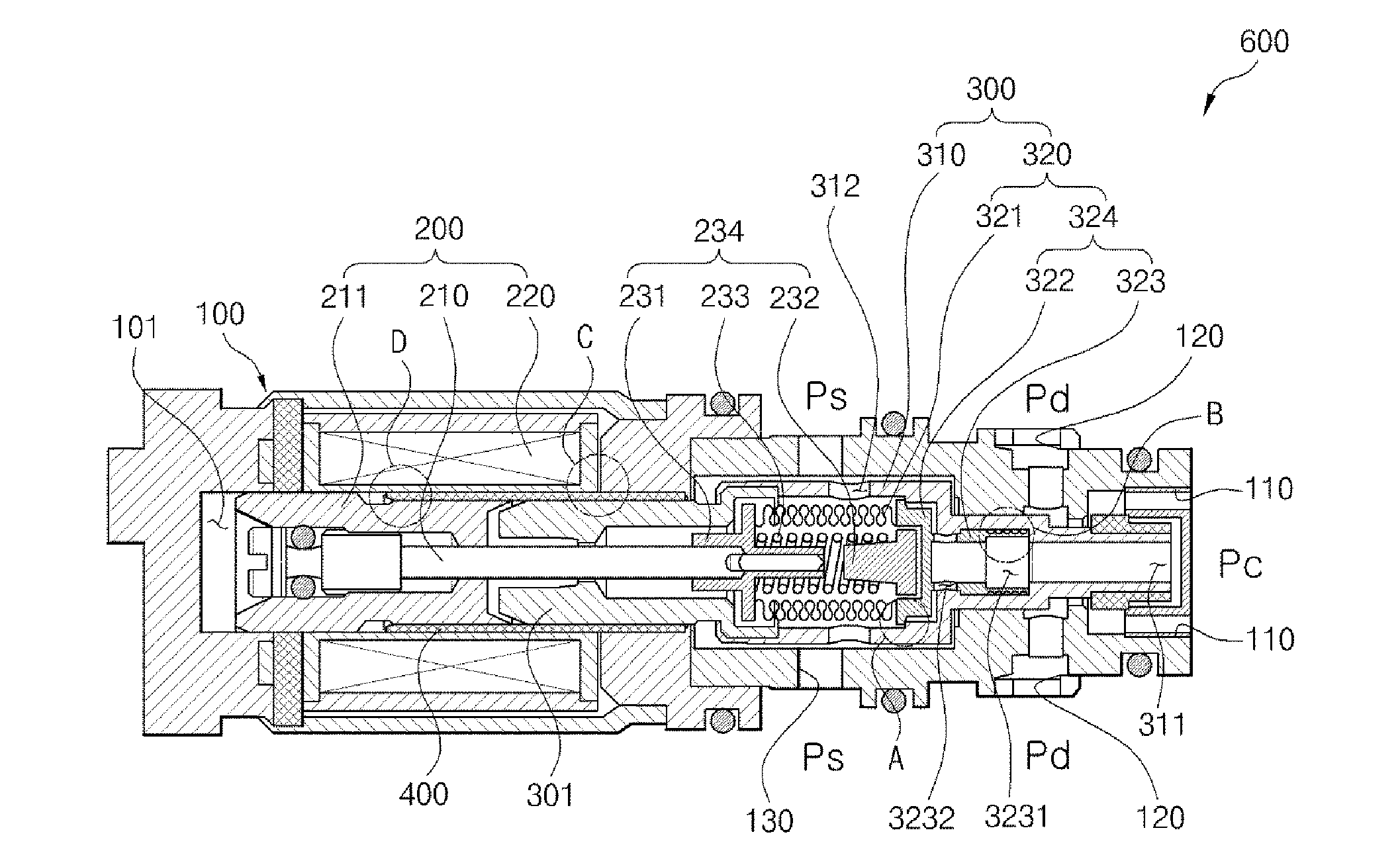
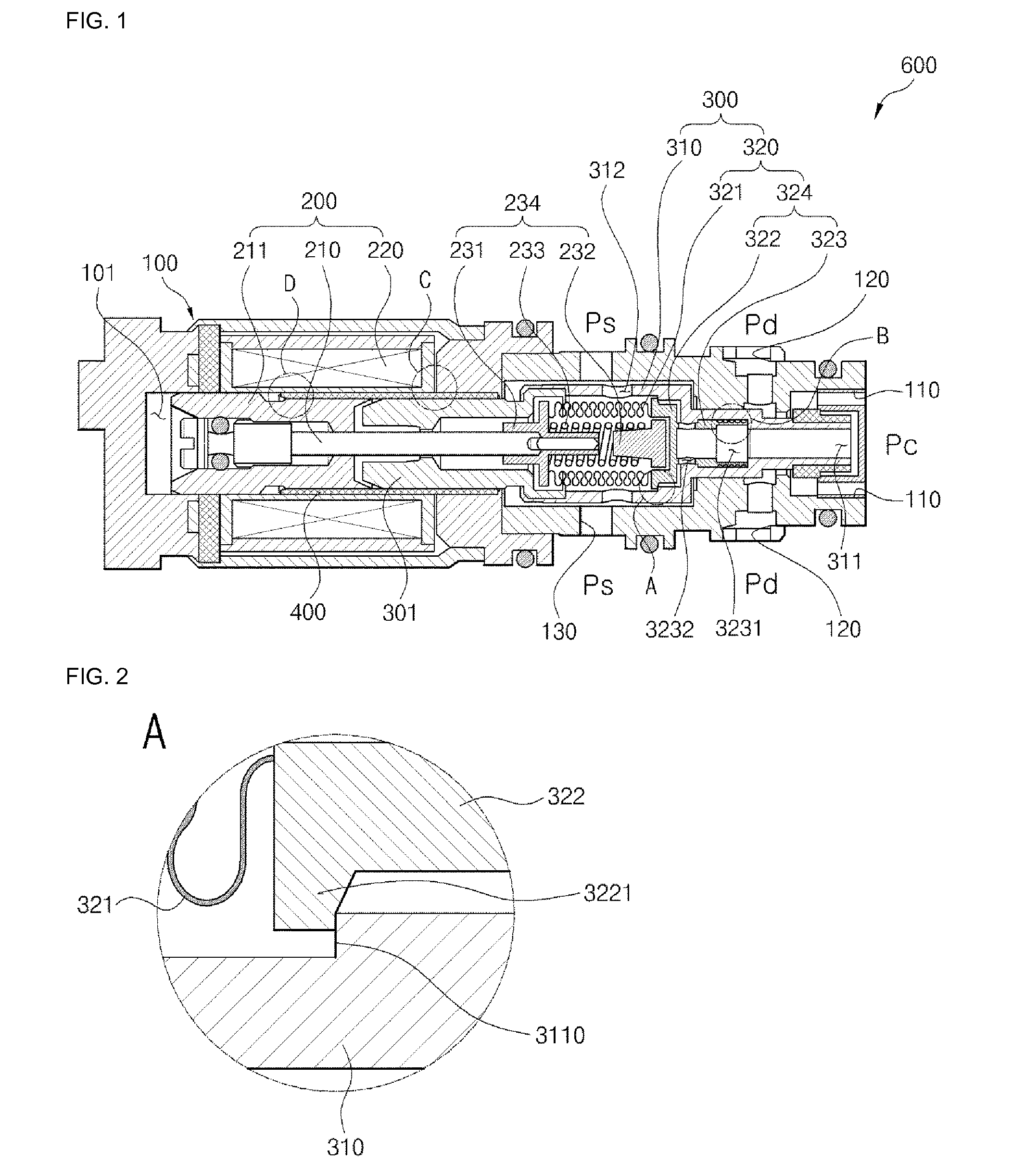
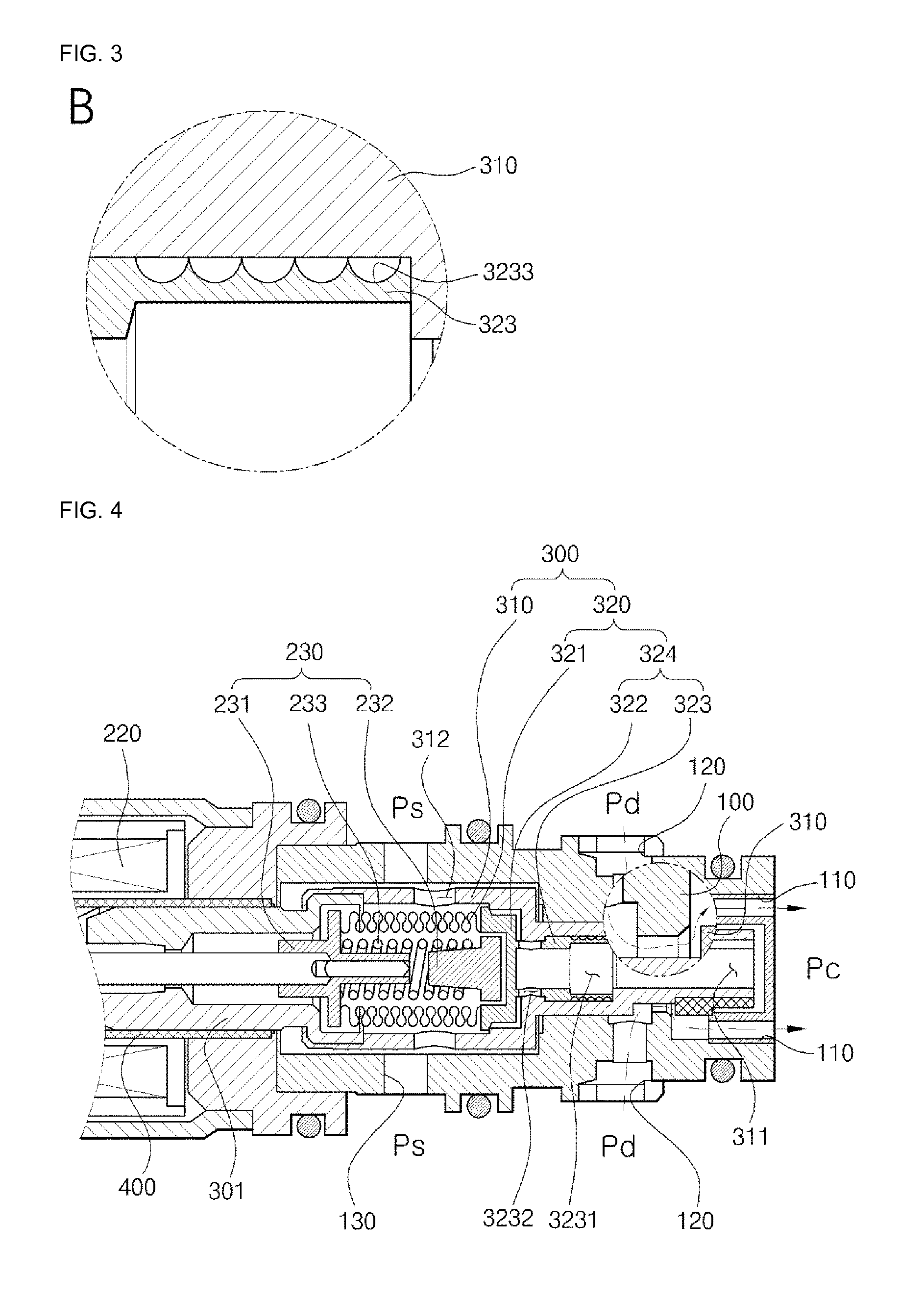
Provided is a control valve for a variable capacity compressor, the control valve including: a valve body including a crank-chamber port, a discharge port, a suction port, a control channel formed inside the control valve such that the crank-chamber port and the discharge port communicate with each other, and a first bleeding channel formed such that the crank-channel port and the suction port communicate with each other; an operating unit provided in the valve body and including a second bleeding channel communicated from a center area to a side surface of the operating unit; and a driving unit provided in the valve body and connected to the operating unit to enable the operating unit to reciprocally move according to a current applied by an external source.

Description

TECHNICAL FIELD[0001]The present invention relates to a control valve for a variable capacity compressor and a method of manufacturing the control valve, and more particularly, to a control valve for a variable capacity compressor and a method of manufacturing the control valve, which are capable of improving performance of the variable capacity compressor.BACKGROUND ART[0002]Generally, swash plate type compressors are widely used as compressors of air conditioning devices for cars, and are classified into various types according to compression methods and structures. Recently, variable capacity compressors that are capable of varying compression capacities are largely used. A capacity of the variable capacity compressor is adjusted by adjusting a gradient of a swatch plate. In other words, the capacity of the variable capacity compressor is reduced as the gradient of the swash plate is reduced by increasing a pressure in a crank chamber when an inflow amount of a refrigerant from a...

Claims


Application Information

Patent Timeline
IPC IPC(8): F04B27/18B23P15/00F04B27/08
CPCF04B27/1804F04B2027/1845B23P15/001F04B27/0895F04B27/14F04B45/02F04B27/18Y10T29/49425Y10T29/49416Y10T137/0491F04B2027/1831F04B2027/1827
Inventor LEE, YONG JULEE, GEON HO
Owner DOOWON TECHN COLLEGE
Learn More