


Quick Research
Generate reliable direction feasibility study reports for your R&D in just a few steps.

Technical Q&A
Discover and master advanced knowledge NOW. Basics, ideas, possibilities, all at once.

Find Solutions
As an expert in R&D theories, this can generate solutions to your technical problems instantly.

Evaluate Feasibility
Analyze your overall solution with one click, know your potential R&D risks in advance.

Monitor Landscape
Get weekly tech updates, stay abreast of the latest tech innovations and key insights.
A valve core structure, faucet and driving system
A driving system and faucet technology, which is applied in the field of faucet spools, can solve the problems of increasing the volume of the water inlet, difficulty in popularization, complex structure, etc., and achieve the effect of increasing the flow rate per unit time, increasing the function of connecting waterways, and overcoming the problem of narrow passages
- Summary
- Abstract
- Description
- Claims
- Application Information
AI Technical Summary
Problems solved by technology
Method used
Image

Examples
Embodiment 1
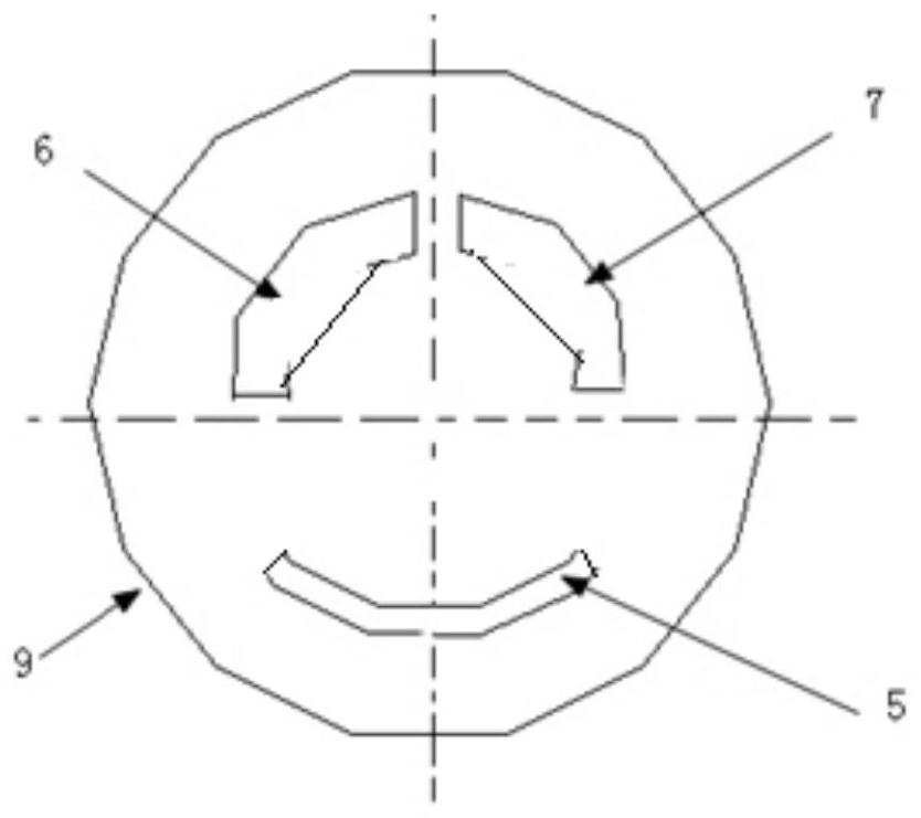
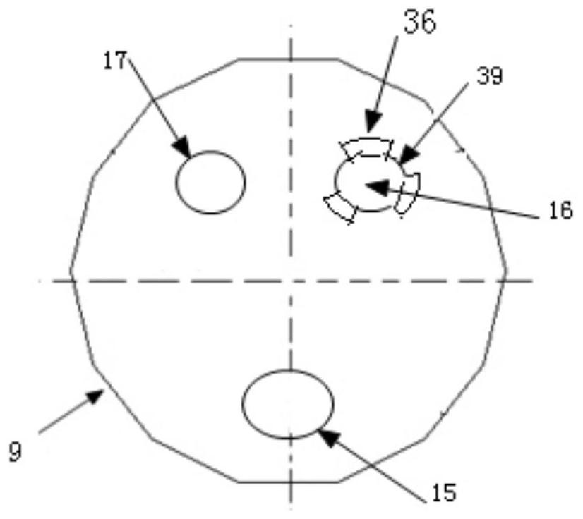
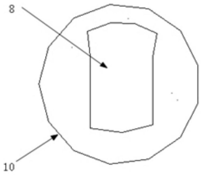
[0088] Spool 2 is in Figure 5 Position: tap water enters the water heater 14 from the tap water interface 28 and the second water pipe 19, hot water enters the first water pipe 18 from the water outlet port 25, extends through the water pipe to the first water inlet 11 of the faucet, and flows through the internal passage 41 of the body 3 to the first Water inlet outer hole 33. The water flow breaks away the sealing surface 34 of the sealing cap 4, and reaches the first water inlet 16 of the fixed part 9 of the valve core 2 along the diversion groove 35 and the diversion groove 39, and communicates with the second water inlet through the groove 8 of the rotating part 10 17. The second water inlet hole 17 is connected to the second water inlet outer hole 44, passes through the second water inlet 12 of the faucet, and then enters the second water pipe 19. The water flow flows along the hot water outlet direction, forming a water flow loop. The water flow is unidirectionally com...
Embodiment 2
[0091] Faucet 27 handle 1 is in such as Figure 4 position, when hot and cold mixed water flows out or only hot water flows out when turning the handle 1 at this position, the control circuit 24 receives the hot water signal from the Hall sensor 22, and then collects the first temperature sensor 20 and the second temperature sensor 21 water temperature signal. Turn the handle 1 as Figure 5 The groove 8 is connected to the first water inlet tank 6 and the second water inlet tank 7 at the right position, the water circuit forms a closed passage, the water pump 23 is started to work, and the water flow is driven to circulate, and the hot water in the water heater 14 enters the first water pipe 18 from the water outlet port 25 to the faucet The first water inlet 11. The water flows through the internal channel 41 of the body 3 to the first water inlet outer hole 33, enters the first water inlet hole 16 of the fixing part 9 through the one-way valve, communicates with the second...
Embodiment 3
[0095] The Hall sensor 22 starts the water pump to work when the water flow per unit time is less than the set value. Pressurizes the water stream to increase flow and improve shower comfort.
PUM
 Abstract
Description
Claims
Application Information
 - R&D Engineer
- R&D Manager
- IP Professional
- Industry Leading Data Capabilities
- Powerful AI technology
- Patent DNA Extraction
Browse by: Latest US Patents, China's latest patents, Technical Efficacy Thesaurus, Application Domain, Technology Topic, Popular Technical Reports.
© 2024 PatSnap. All rights reserved.Legal|Privacy policy|Modern Slavery Act Transparency Statement|Sitemap|About US| Contact US: help@patsnap.com