
Dust removal method

A dust removal device and dust content technology, applied in the direction of separation methods, chemical instruments and methods, gravity filters, etc., can solve the problems of limited filter area improvement, small-area porous film waste, and low-cost filter area. Achieve the effects of low cost, narrow working surface and high filtration temperature

Pending Publication Date: 2021-01-19
CHENGDU INTERMENT TECH
View PDF10 Cites 0 Cited by
  • Summary
  • Abstract
  • Description
  • Claims
  • Application Information

AI Technical Summary

Problems solved by technology

[0005] (1) The inside or outside of the filter element is provided with a support body, which significantly increases the weight and cost;
[0006] (2) Due to the large diameter of the filter element, the sealing of both ends of the filter element is particularly complicated (such as the inner filter filter device published by the Chinese invention patent with the application number of 2018103243431), and once the filter element is damaged, it is usually replaced directly due to the difficulty of repair. very high cost;
[0007] (3) The diameter of the filter element is large, and the filter device requires a large footprint;
[0008] (4) If you want to reduce the seams to improve the strength of the filter element, you need to make the porous film before rolling have a very large area, which not only significantly increases the production cost, but also causes waste of small-area porous film after cutting;
[0009] (5) Since the filter element is very long, and the added support body significantly increases in weight, the handling and installation of the filter element requires the cooperation of multiple staff, which is time-consuming and laborious;
[0010] (6) When the filter element is very long, the uniformity of the blowback effect along the axial distribution of the filter element becomes worse;
[0011] (7) Due to limiting factors such as the site, the filter area of ​​the filter element is limited.
[0012] However, there is no effective and low-cost means to increase the filtration area and strength of the filter element rolled from sheet-like materials, except for increasing the diameter and length and setting the support body.

Method used


Image

  • Dust removal method
  • Dust removal method
  • Dust removal method

Examples


preparation example Construction

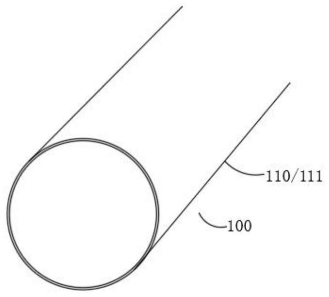
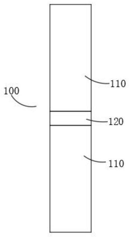
[0134] In addition, the present invention provides a method for preparing the above-mentioned filter tube 100, which includes the steps of: rolling a thin sheet material 111 with a thickness of 0.2-2.5 mm into a tube body 110 with an outer diameter of 20-200 mm, fixing and sealing the seam 112 Welded or glued.

[0135] Figure 4 It is a tube body obtained by rolling in a specific embodiment. Such as Figure 4 As shown, the seam 112 of the tube body 110 is parallel to the central axis of the filter tube 100 , and the tube body 110 is obtained by butting the long side of the rectangular sheet material 111 whose wide side matches the diameter of the tube body 110 .

[0136] Figure 5 It is a tube body obtained by rolling in another specific embodiment. Such as Figure 5 As shown, the seam 112 of the pipe body 110 is in the shape of a helix. The pipe body 110 is prepared by the preparation method published in the Chinese invention patent with the application number 2019102093...

specific Embodiment approach

[0204] Figure 20-21 It is a structural schematic diagram of the first specific embodiment of the pressing mechanism. Such as Figure 20-21 As shown, the pressing mechanism includes: a pressing plate 441, the upper joint 210 and the step 330 are clamped between the pressing plate 441 and the first support structure 420; a pressing assembly, the pressing assembly is connected The pressing plate 441 and the first support structure 420 . in, Figure 20 Push-in installation from top to bottom, Figure 21 Push-in installation from bottom to top.

[0205] Figure 22 It is a structural schematic diagram of the second specific embodiment of the pressing mechanism. Such as Figure 22 As shown, the pressing mechanism includes: a pressing plate 441, the step 330 is clamped between the pressing plate 441 and the first support structure 420; a pressing assembly, the pressing assembly is connected to the pressing assembly. Plate 441 , upper joint 210 and first support structure 420 ...


PUM

PropertyMeasurementUnit
thicknessaaaaaaaaaa
pore sizeaaaaaaaaaa

Abstract

The invention discloses a dust removal method which is characterized in that a dust removal device is adopted, the dust removal device comprises a filter structure, the filter structure comprises a filter element, the filter element comprises filter tubes, and tube bodies of the filter tubes are formed by shaping metal or a sheet-shaped material taking metal as a matrix in a rolled manner and sealing and processing joints; the outer diameter of the tube bodies is only 20-200 mm, and the distance between every two adjacent filter tubes is 5-100 mm; the filtering wind speed is 0.8-2 m / min, and the temperature of gas to be filtered is less than or equal to 800 DEG C. Due to the adoption of a filtering structure with a larger filtering area, the filtering resistance is smaller, and the filtering wind speed is lower; the tube bodies made of the metal or the sheet-shaped material taking the metal as the matrix is adopted, so the filter element has the filtering resistance obviously smaller than that of a ceramic filter element, and can bear the filtering temperature far higher than that of a non-metal cloth bag. Therefore, compared with the prior art, the dust removal method solves the problems that a non-metal cloth bag is not resistant to high temperature and not high in precision, and the technical problem that the filtering resistance is large due to small filtering area is solved.

Description

[0001] This application claims the priority of the first application in China with the application number 2020102681879, the application date is April 8, 2020, and the title is "filter tube, cluster filter element and its application". technical field [0002] The invention relates to the technical field of flake materials and filtration, in particular, to a dust removal method. Background technique [0003] Sheet-shaped materials have significantly better high-temperature resistance than non-metallic cloth bags and lower filtration resistance than ceramic filter elements, so tubular filter elements rolled from sheet-shaped materials are widely used. [0004] The patent publication numbers that the applicant of the present application has submitted are CN104759630A, CN104759629A, CN104874798A, CN104959611A, CN104959612A and CN104874801A and other Chinese invention patent applications disclose unsupported or supported (referring to raw material powder is attached on the suppor...

Claims


Application Information

Patent Timeline
Patent Type & Authority Applications(China)
IPC IPC(8): B01D46/24B01D46/00B01D29/68B01D29/52B01D29/31B01D50/00
CPCB01D46/24B01D29/31B01D50/00B01D29/52B01D29/68B01D46/58
Inventor 高麟蒋敏王韬莫代林
Owner CHENGDU INTERMENT TECH
Learn More