Energy-saving assembled machine room and dynamic loop control system thereof

A control system and machine room technology, applied in the direction of control/adjustment system, non-electric variable control, and simultaneous control of multiple variables, etc., can solve the problems of high cost, long construction period, and large pollution, and achieve the goal of reducing the proportion of power consumption Ratio, reduce the spread of noise, reduce the effect of power consumption

Pending Publication Date: 2021-01-15
GUANGDONG PLANNING & DESIGNING INST OF TELECOMM
View PDF0 Cites 0 Cited by
  • Summary
  • Abstract
  • Description
  • Claims
  • Application Information

AI Technical Summary

Problems solved by technology

[0003] This kind of construction method will have the following problems: ①, the pollution to the surrounding environment is relatively large, and the construction period is relatively long, and the construction is difficult, especially in the winter rainy season; ②, brick-concrete or concrete walls The natural heat absorption and heat dissipation coefficient of the communication equipment room is very high, so the communication equipment room needs to spend a lot of electricity to maintain the indoor temperature. For example, in order to reduce the temperature generated by the operation of the equipment, the power consumption in the equipment room in summer accounts for 58% of the overall electrical energy consumption of the equipment room. The power loss due to the heat transfer on the wall of the isolated computer room accounts for 42%, and the heat transfer factor accounts for about 40% of the electricity consumption of the air conditioner; ③, the operation of equipment in the computer room will generate a lot of noise, which will easily affect the daily life of the surrounding residents

Method used


Image

  • Energy-saving assembled machine room and dynamic loop control system thereof
  • Energy-saving assembled machine room and dynamic loop control system thereof
  • Energy-saving assembled machine room and dynamic loop control system thereof

Examples


Embodiment 1

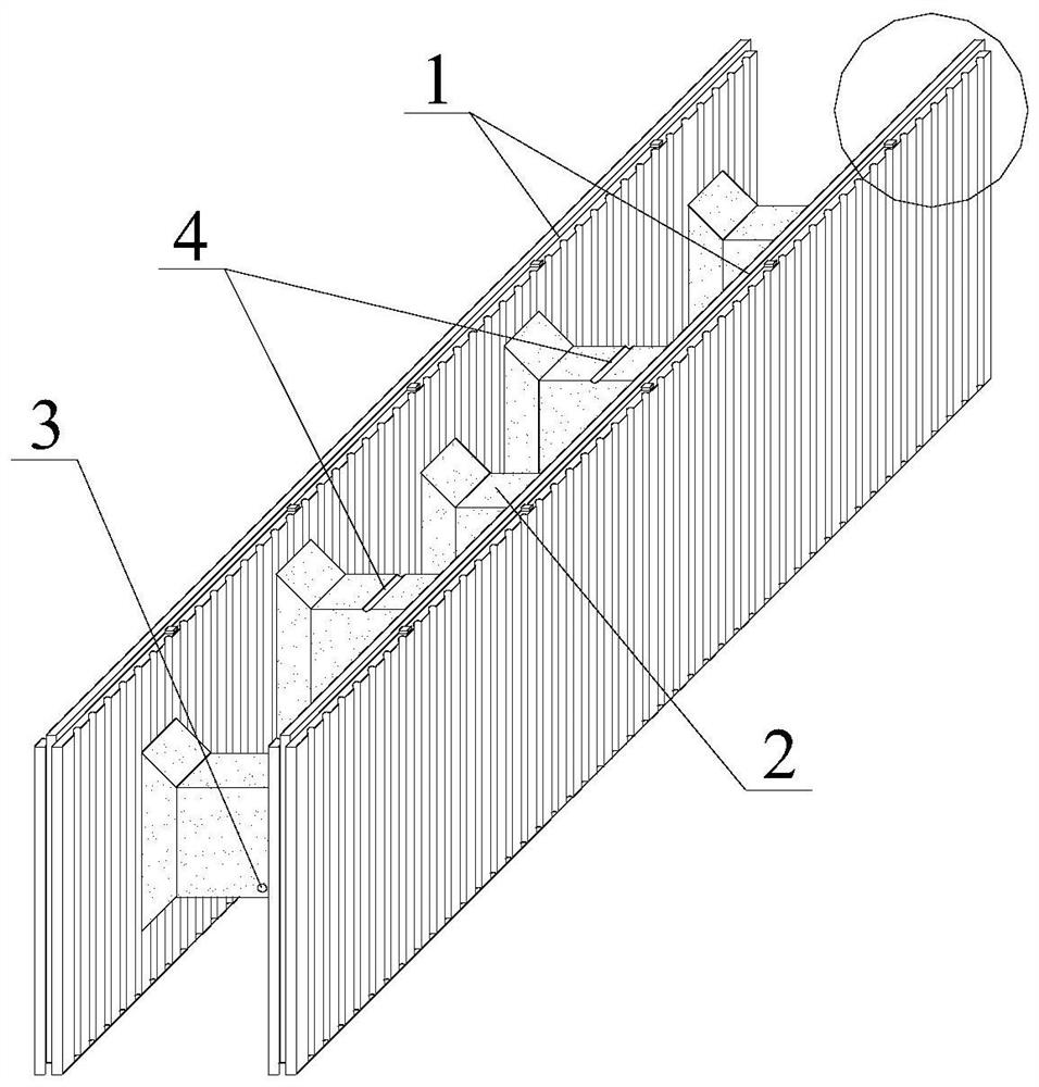
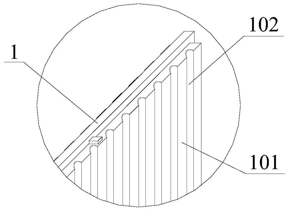
[0034] see figure 1 As shown, in the first implementation of the present invention regarding the specific structural form of the machine room wall, the machine room wall is a flat plate, and the flat plate includes a plate base 1 and an intermediate connecting column 2 fixedly arranged between the plate bases 1, wherein , the plate substrate 1 is a flat structure. In the solution of this embodiment, the flat plate is used as the wall structure arranged on the side of the energy-saving assembled machine room of the present invention, and the whole is arranged as a flat structure. Specifically, the plate is 240mm wide, 300mm high, and 900mm long. The two plate substrates 1 arranged in parallel are connected through the middle pillar 2, and the reinforcement holes reserved on the side of the middle pillar 2 can be used between each plate and the plate. 3 are horizontally connected together, or are stacked up and down through the reinforced holes 3 reserved on the upper and lower...

Embodiment 2

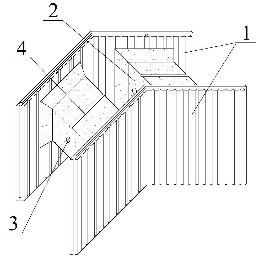
[0036] see image 3 As shown, in the second implementation of the present invention regarding the specific structural form of the machine room wall, the machine room wall is a corner plate, and the corner plate includes a plate base 1 and an intermediate connecting column 2 fixedly arranged between the plate bases 1, wherein , the plate base 1 is a flat structure and the plate base 1 forms an included angle of 90°. In the solution of this embodiment, the flat panels are used as the wall structure connecting each flat panel in the energy-saving assembled machine room of the present invention, and the whole is arranged as an L-shaped structure arranged at 90°. Specifically, the included angle of the corner plate is 90°, the width is 240mm, the equal length of both sides is 310mm, and the height is 300mm. The reinforced holes 3 reserved on the sides of the middle pillar 2 are horizontally connected together, or the reinforced holes 3 reserved on the upper and lower sides of the ...

Embodiment 3

[0038] see Figure 4 As shown, in the third implementation of the present invention about the specific structural form of the machine room wall, the machine room wall is a roof plate, and the roof plate includes a plate base 1 and a raised connecting column 5 fixedly arranged on the side of the plate base 1. The side and / or upper and lower sides of the connecting column 5 are provided with a number of reinforcement holes 3 . In the solution of this embodiment, the roof plate is used as the top wall structure in the energy-saving assembled machine room of the present invention, and the whole is also a flat plate structure. Specifically, the length and width of the roof plate are both 800mm and 120mm thick, and the side of the plate base 1 is provided with a raised connecting column 5, and the side and / or upper and lower sides of the raised connecting column 5 are reserved with reinforcement holes 3 , for the insertion of horizontal steel bars and longitudinal steel bars respec...


PUM


Abstract

The embodiment of the invention provides an energy-saving assembled machine room and a dynamic loop control system thereof. The energy-saving assembled machine room comprises machine room walls, the machine room walls comprise plate base bodies, each plate base body comprises an EPS honeycomb isolation thermal insulation material, a flame retardant and coal cinder powder, the EPS honeycomb isolation thermal insulation material, the flame retardant and the coal cinder powder are mixed according to a certain proportion to form material particles, and relatively independent isolation cabins are formed among the material particles. The energy-saving assembled machine room is formed by splicing and connecting the multiple machine room walls through steel bars and has the advantages of being high in fireproof performance, obvious in noise reduction effect, short in construction period, small in pollution and the like. The dynamic loop control system with the real-time monitoring and real-time controlling functions has the advantage that it is guaranteed that communication equipment in the energy-saving assembled machine room can stably operate under the preset working condition at any time.

Description

technical field [0001] The invention relates to the technical field of communication machine room construction, in particular to an energy-saving assembled machine room and a dynamic ring control system thereof. Background technique [0002] The communication room is a room mainly used to carry the main communication equipment of mobile, telecom, China Unicom and other operators, as well as supporting power supply, transmission and other equipment. The internal physical environment needs to be strictly controlled, which is mainly divided into several aspects: Temperature, power, floors, fire protection systems, etc. The common communication room usually adopts the traditional brick or concrete structure. Specifically, it is constructed by transfer or concrete on site according to the design drawings. The construction method is similar to that of ordinary brick-concrete structure houses. [0003] This kind of construction method will have the following problems: ①, the pollu...

Claims


Application Information

Patent Timeline
Patent Type & Authority Applications(China)
IPC IPC(8): E04H5/02E04B2/00E04B2/86E04B1/80E04B1/94G05D27/02
CPCE04B1/80E04B1/942E04B2/00E04B2/8635E04H5/02G05D27/02
Inventor 霍励佟巍曹龙胤信劲松李建伟王浩杨小彦黄伟如金成伟郑建飞曾沂粲
Owner GUANGDONG PLANNING & DESIGNING INST OF TELECOMM
Why Eureka
Try Eureka