
Catalyst

a technology of catalysts and catalysts, applied in the field of catalysts, can solve the problems of relatively large installation space of catalysts and relatively long construction in the main throughflow direction, and achieve the effects of reducing heat dissipation, reducing heat dissipation, and shortening the development length of the boundary layer

Inactive Publication Date: 2005-09-15
ALSTOM TECH LTD
View PDF9 Cites 32 Cited by
  • Summary
  • Abstract
  • Description
  • Claims
  • Application Information

AI Technical Summary

Benefits of technology

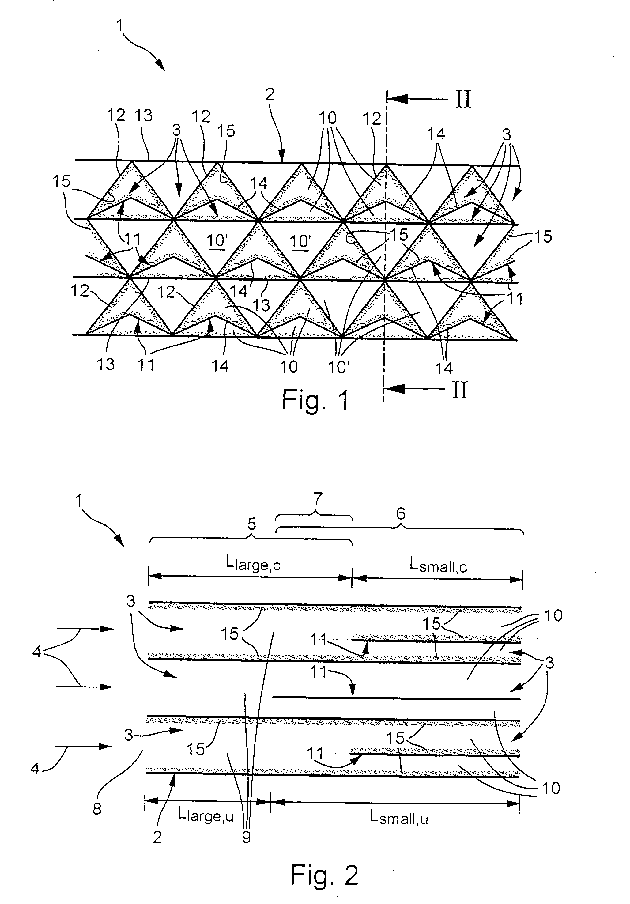
[0007] The invention is based on the general concept of forming the succeeding channels which are equipped with the smaller internal cross-sectional areas by introducing separation walls into channels in the succeeding sector which extend into the inlet sector, where they form the inlet channels. In this way, the channels provided with the separation walls in the succeeding sector are divided into two or more succeeding channels, which each have a smaller internal cross-sectional area than the inlet channels. The outlay involved in producing a catalyst of this type is relatively low, since given a suitable design the separation walls can be integrated in the succeeding sector relatively easily. Moreover, the proposed design makes it possible to achieve a relatively high cell density, which increases the conversion rate and reduces the dimensions of the catalyst.
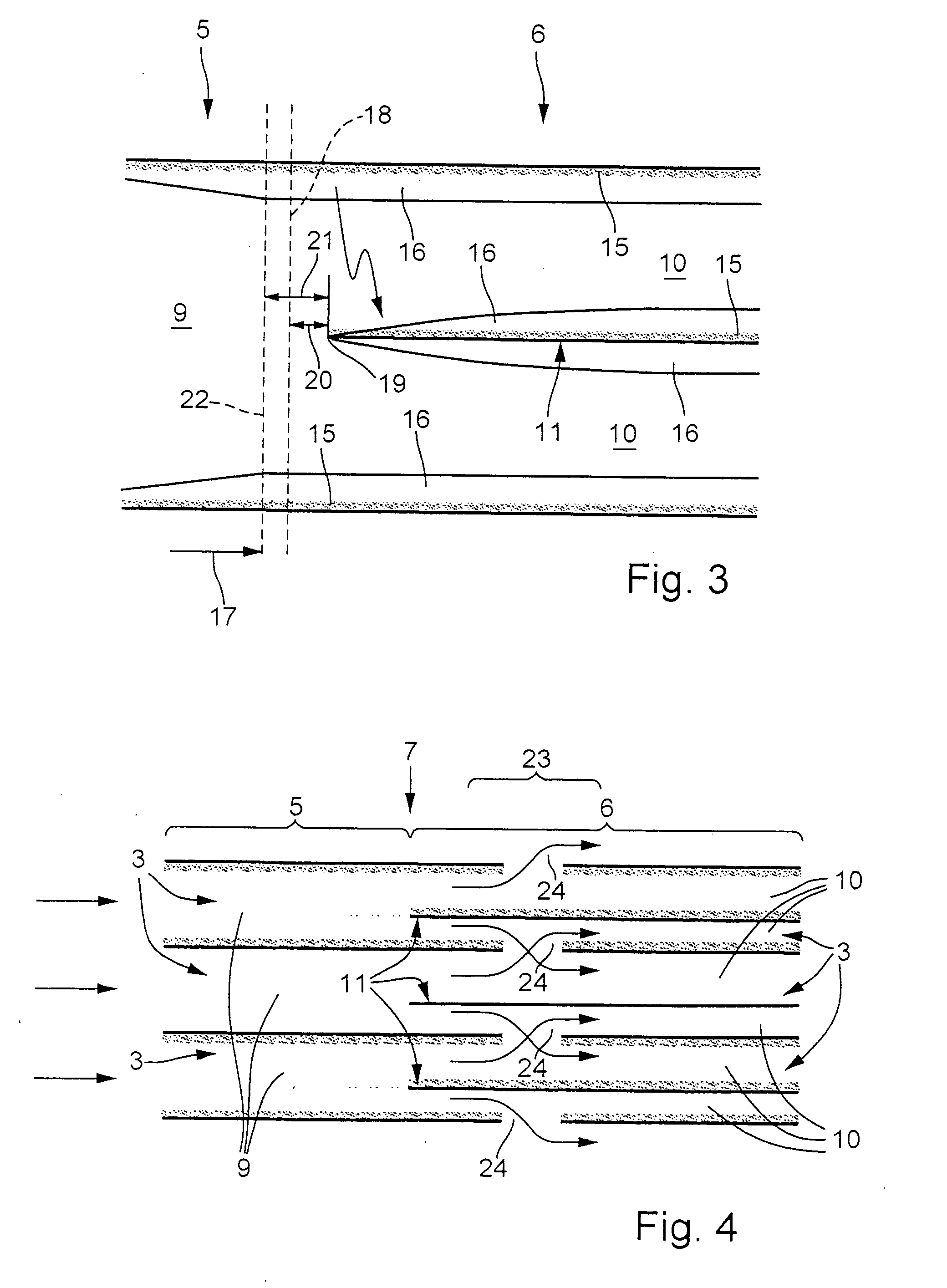
[0009] The catalyst can also be configured in such a way that the length of the inlet sector in the main throughflow direction is greater than the development length of a hydrodynamic boundary layer which is formed in the channels in a rated operating state of the catalyst, in particular of the burner equipped with the catalyst. This design takes account of the fact that a diffusion-limited or diffusion-controlled reaction (tends to) form(s) in a developed boundary layer flow. Furthermore, this takes account of the knowledge that with larger internal cross-sectional areas, the development length of the boundary layer is shorter, on account of the faster conversion from laminar flow to turbulent flow, and that only a reduced dissipation of heat is possible in a developed boundary layer compared to a boundary layer which is still developing. Accordingly, a heterogeneous catalyst reaction can be ignited in the inlet channels having the larger internal cross-sectional areas even over a short length. Consequently, the overall catalyst is of relatively short construction.
[0010] In a refinement, the dimensioning of the catalyst is deliberately selected in such a way that there is a predetermined distance between the location beyond which, in the rated operating state of the catalyst, the diffusion-controlled surface reaction is present and / or beyond which, in the rated operating state of the catalyst, a developed hydrodynamic boundary layer is present and a transition from the inlet sector to the succeeding sector, which predetermined distance is selected in such a way that the heterogeneous combustion reaction is not extinguished in the catalytically active succeeding channels in the rated operating state of the catalyst. Since a very much larger surface area and—depending on the particular embodiment—considerably improved cooling are present at the transition to the succeeding channels, a transition which lies too close to the development length of the boundary layer or too close to the ignition point of the heterogeneous catalyst reaction could lead to the heterogeneous reaction being extinguished.
[0011] A particularly inexpensive structure can be achieved for the catalyst according to the invention in particular if the channels are formed by corrugated and / or folded channel plates which are layered on top of one another transversely with respect to the main throughflow direction and the corrugations and / or folds of which extend in the main throughflow direction. The separation walls are in this case formed by separation plates which are arranged transversely with respect to the main throughflow direction between two adjacent channel plates in the succeeding sector. The plates are designed to be catalytically active on at least one side, such that when the catalyst is assembled both catalytically active inlet channels and catalytically active succeeding channels are present. With this design, the separation walls in the form of the separation plates can be integrated in the catalyst even as early as while the catalyst is being built. This considerably simplifies production of the sectors with channels of different internal cross-sectional areas.
[0014] In an advantageous refinement, however, the catalyst has catalytically inactive succeeding channels with a smaller internal cross-sectional area. Installing the separation walls in the catalytically inactive succeeding channels as well allows the flow resistance of the catalytically inactive succeeding channels to be influenced, so that it is possible to influence the distribution of the flow fed to the catalyst between the catalytically active channels and the catalytically inactive channels. By way of example, a distance from the catalyst inlet to the beginning of the catalytically inactive succeeding channels with a smaller internal cross-sectional area may be greater than a distance from the catalyst inlet to the beginning of the catalytically active succeeding channels with a smaller internal cross-sectional area. In this embodiment, the pressure drop in the catalytically active succeeding channels is lower than in the corresponding catalytically inactive succeeding channels. The mass flow of combustible fuel-oxidant mixture through the catalytically active channels is correspondingly greater, with the result that a greater conversion rate of the fuel can be achieved. If, by contrast, the distance from the catalyst inlet to the beginning of the catalytically inactive succeeding channels with a smaller internal cross-sectional area is less than the distance from the catalyst inlet to the beginning of the catalytically active succeeding channels, the pressure drop is lower in the catalytically inactive succeeding channels. This leads to reduced flow velocities in the catalytically active succeeding channels, which allows the heterogeneous reaction to be ignited at relatively low temperatures. Irrespective of their length, the separation walls used to form the catalytically inactive succeeding channels with smaller internal cross-sectional areas can improve the dissipation of the heat which is formed in the catalytically active succeeding channels, since the intermediate walls are heated by the heat radiated from the walls of the adjacent catalytically active channels and at the same time have the cooling mixture flowing around them.
[0015] Moreover, narrower succeeding channels, i.e. those succeeding channels which have a smaller internal cross-sectional area, impede spontaneous ignition of a homogeneous combustion reaction in the fuel-oxidant mixture within the succeeding channels, since with smaller internal cross-sectional areas radicals which are formed during the heterogeneous combustion reaction can be bonded more successfully, an action which is also described as an improvement to the “radical quenching” (elimination of radicals).

Problems solved by technology

The known catalysts generally require a relatively large installation space, which may not be available in certain installation situations, in particular in the case of a burner of a power plant.
In particular if a relatively high degree of conversion of the fuel carried in the mixture is to be achieved during flow through the catalyst, this generally leads to a relatively long construction in the main throughflow direction.

Method used


Image

  • Catalyst
  • Catalyst
  • Catalyst

Examples


Embodiment Construction

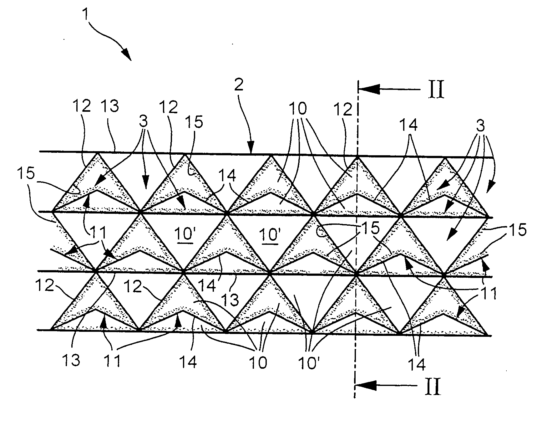
[0022] In accordance with FIGS. 1 and 2, a catalyst 1 according to the invention has a structure 2 which has or forms a plurality of channels 3 which run parallel to one another and parallel to a main throughflow direction 4, indicated by arrows in FIG. 2, of the catalyst 1. In the specific embodiment shown here, moreover, the channels 3 run in a straight line.

[0023] As can be seen from FIG. 2, the catalyst 1 or its structure 2 is divided into at least two sectors, namely an upstream first sector 5 and a downstream second sector 6, as seen in the main throughflow direction 4. The sectors 5, 6 are marked by curly brackets in FIG. 2, making it clear that the two sectors 5, 6 overlap in a transition region 7 which is likewise marked by a curly bracket. The upstream first sector 5 includes an inlet 8 of the catalyst 1 and is therefore also referred to below as inlet sector 5, whereas the downstream second sector 6 is also referred to below as succeeding sector 6. Accordingly, the inlet...


PUM

PropertyMeasurementUnit
distanceaaaaaaaaaa
areaaaaaaaaaaa
cross-sectional areaaaaaaaaaaa

Abstract

The present invention relates to a catalyst (1) for combustion of at least a portion of a gaseous fuel-oxidant mixture flowing through the catalyst (1), in particular for a burner of a power plant. An inlet sector (5) comprises inlet channels (9). A succeeding sector (6) comprises succeeding channels (10). The succeeding channels (10) have smaller internal cross-sectional areas than the inlet channels (9). To improve the production of the catalyst (1), the invention proposes channels (3) which extend through the inlet sector (5) and through the succeeding sector (6) and have the internal cross-sectional area of the inlet channels (9). The inlet channels (9) are formed by portions of the channels (3) lying in the inlet sector (5). The succeeding channels (10) are provided by arranging separation walls (11) within portions of the channels (3) lying in the succeeding sector (6), the separation walls (11) dividing each of the respective channel portions in the succeeding sector (6) into two succeeding channels (10).

Description

FIELD OF THE INVENTION [0001] The present invention relates to a catalyst for combustion of a portion of a gaseous fuel-oxidant mixture flowing through the catalyst, in particular for a burner of a power plant, having the features of the preamble of claim 1. DISCUSSION OF BACKGROUND [0002] U.S. Pat. No. 4,154,568 has disclosed a catalyst of the type described in the introduction, the body of which is composed of a plurality of part-bodies arranged one behind the other in a main throughflow direction of the catalyst. The individual part-bodies are in each case designed as monoliths which in each case form a sector of the catalyst. The monolith through which medium flows first therefore includes an inlet of the catalyst and therefore forms an inlet sector, while the following monoliths form succeeding sectors. The individual monoliths include channels, also referred to as cells. In the known catalyst, the cell density increases in the main throughflow direction, while the cell size de...

Claims


Application Information

Patent Timeline
Patent Type & Authority Applications(United States)
IPC IPC(8): B01J8/00
CPCB01J2219/3221B01J2219/32466B01J35/04B01J35/006F23C13/00B01J35/393B01J35/56
Inventor CARRONI, RICHARDGRIFFIN, TIMOTHY
Owner ALSTOM TECH LTD
Learn More