Eureka AIR delivers breakthrough ideas for toughest innovation challenges, trusted by R&D personnel around the world.

Punch forming device for metal cover of food packaging tin

A technology for stamping and forming and food packaging, applied in the field of stamping devices, can solve the problems that the to-be-stamped parts are easily adhered to the upper and lower stamping dies, the to-be-stamped parts are prone to shaking, and consumes a lot of human resources, so as to avoid shaking. , The structure design is reasonable, the effect of saving human resources

Active Publication Date: 2021-01-12
SHANDONG HUANQIU TINPLATE CAN MAKING
View PDF11 Cites 3 Cited by
  • Summary
  • Abstract
  • Description
  • Claims
  • Application Information

AI Technical Summary

Problems solved by technology

[0003] At present, when the metal cover is stamped and formed, the parts to be stamped are placed on the lower stamping die manually, and then the upper stamping die moves downward to carry out the stamping work. After the stamping is completed, the parts to be stamped are manually removed. Under the circumstances, this method not only needs to consume more human resources, but also has potential safety hazards in the stamping process, which may easily cause injuries to operators. It is easy to shake and affect the stamping quality

Method used


Image

  • Punch forming device for metal cover of food packaging tin
  • Punch forming device for metal cover of food packaging tin
  • Punch forming device for metal cover of food packaging tin

Examples


Embodiment

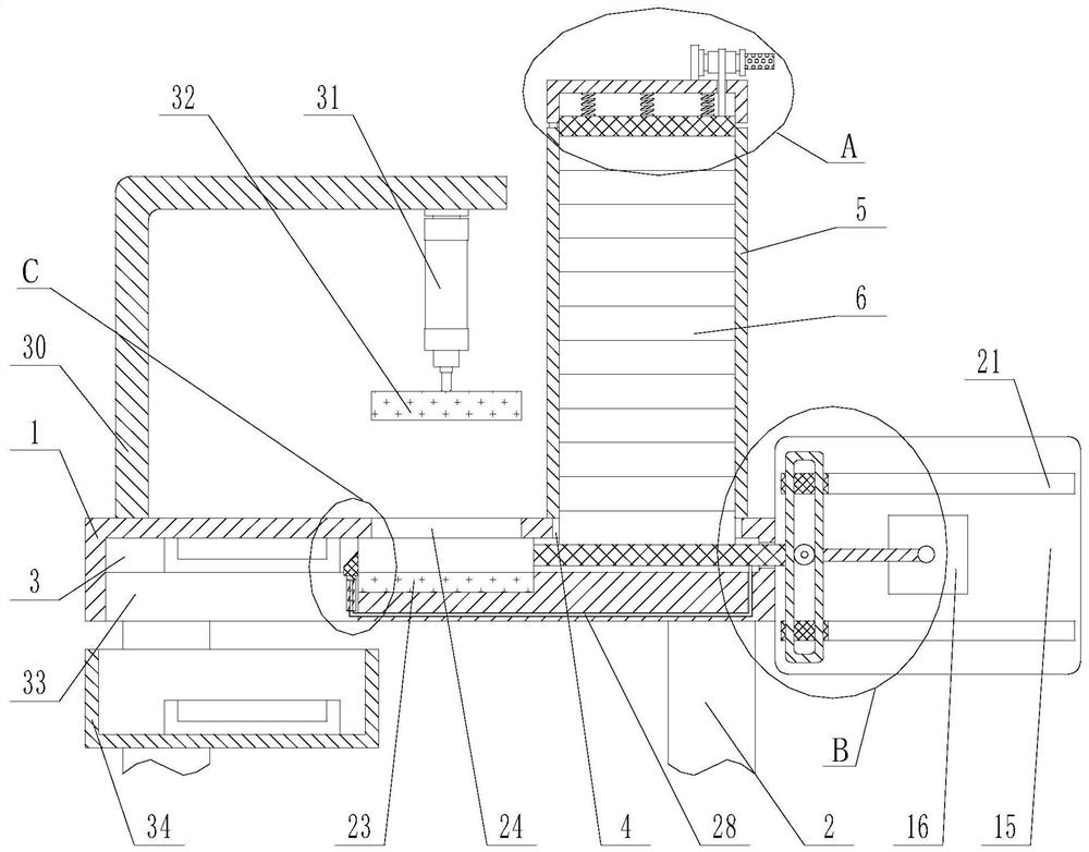
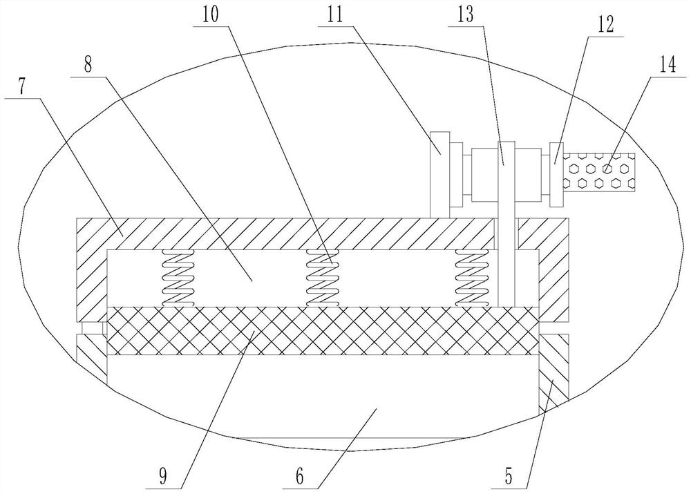
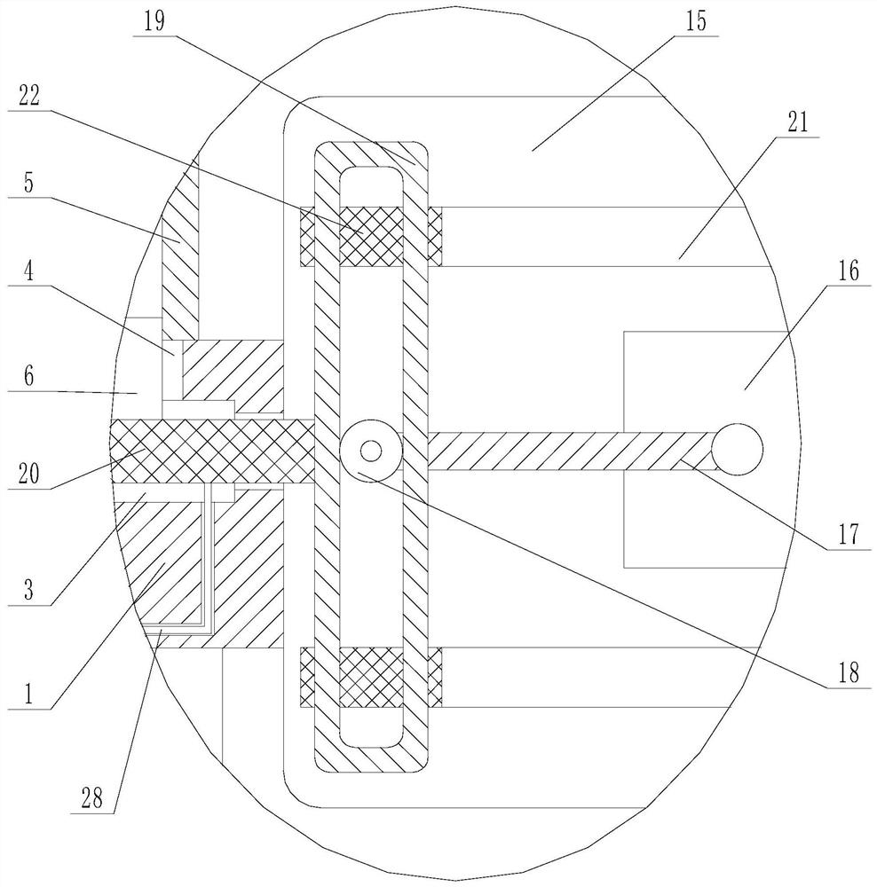
[0025]Such asFigure 1-5As shown, a stamping and forming device for a metal lid of a food packaging can includes a worktable 1 and a part to be stamped 6. The bottom of the worktable 1 is fixedly connected with four support legs 2, and the worktable 1 is provided with a guide groove 3 for working The upper end of the table 1 is provided with a communicating groove 4, and the upper end of the working table 1 is fixedly connected with a storage mechanism opposite to the communicating groove 4, and the stamping part 6 is placed in the storage mechanism. The storage mechanism includes a fixed connection to the upper end of the working table 1. And the storage box 5 opposite to the communicating groove 4, the to-be-punched part 6 is placed in the storage box 5. It should be noted that the to-be-punched part 6 at the bottom passes through the communicating groove 4 and extends into the guide groove 3 , The upper end of the storage box 5 is rotatably connected with a cover 7, and the bottom...


PUM


Abstract

The invention discloses a punch forming device for a metal cover of a food packaging tin, and belongs to the technical field of punching devices. The punch forming device solves the defects that in the prior art, a to-be-punched part of a traditional punch forming device is prone to adhering to an upper punching die and a lower punching die, the punching quality is affected as the to-be-punched part is prone to shaking in the punching process. A main structure of the punch forming device comprises a worktable and a to-be-punched part, wherein a guide groove is formed in the worktable, a communicating groove is formed in the upper end of the worktable, a storage mechanism opposite to the communicating groove is fixedly connected to the upper end of the worktable, the to-be-punched part is placed in the storage mechanism, and a pushing mechanism is fixedly connected to the side wall of the worktable. The pushing mechanism penetrates through the side wall of the guide groove and extends into the guide groove, the lower punching die is arranged at the inner bottom of the guide groove, a punching groove communicating to the guide groove is formed in the upper end of the worktable in a penetrating mode, and a discharging groove communicating to the guide groove is formed in the bottom of the worktable. The punch forming device is mainly used for punching the metal cover of the food packaging bin.

Description

Technical field:[0001]The invention belongs to the technical field of stamping devices, and specifically relates to a stamping and forming device for a metal lid of a food packaging can.Background technique:[0002]Stamping can obtain parts with thin walls, light weight, good rigidity, high surface quality, and complex shapes that other processing methods cannot or are difficult to manufacture. In the production and processing of metal lids for food packaging cans, they usually need to be stamped Molding process.[0003]At present, when the metal cover is stamped and formed, the parts to be stamped are manually placed on the lower stamping die, and then moved downward through the upper stamping die to perform the stamping work. After the stamping is completed, the parts to be stamped are manually taken out manually. Next, this method not only requires a lot of human resources, but also has potential safety hazards during the stamping process, which is likely to cause injury to the opera...

Claims


Application Information

Patent Timeline
IPC IPC(8): B21D51/44B21D43/00B21D43/20B21D43/02
CPCB21D51/44B21D51/446B21D43/003B21D43/20B21D43/027
Inventor 杨明青周德民
Owner SHANDONG HUANQIU TINPLATE CAN MAKING
Why Eureka
Eureka Blog
Learn More