
Circuit board production equipment based on vacuum etching technology

A technology for production equipment and circuit boards, which is applied to printed circuits, printed circuit manufacturing, electrical components, etc., can solve the problems of high equipment cost, power consumption, reduced circuit board etching effect, and high requirements for the use environment, so as to reduce maintenance difficulty, Improved maintenance efficiency and low environmental requirements

Active Publication Date: 2021-06-22
东莞感恩蚀刻科技有限公司
View PDF7 Cites 0 Cited by
  • Summary
  • Abstract
  • Description
  • Claims
  • Application Information

AI Technical Summary

Problems solved by technology

[0003] The existing patent No. CN102092955A proposes an etching device, which has the advantage of reducing the occurrence of etching defects, but it lacks the effect of effectively cleaning the etching environment and impurities on the circuit board and effectively recovering the etching solution before and during etching. The problem that the etching effect of the circuit board is reduced and the efficiency of the front and rear processing is reduced
[0004] The existing patent No. CN103208438A proposes an etching device, which has the advantages of saving costs, shortening the manufacturing process time and increasing production capacity, but it uses various electrical components such as vacuum pumps, pneumatic cylinders and conveying components, so that it has high Equipment cost and power consumption, as well as high equipment volume, and the above conditions make the use conditions of the equipment lead to the problem of high requirements for the use environment

Method used


Image

  • Circuit board production equipment based on vacuum etching technology
  • Circuit board production equipment based on vacuum etching technology
  • Circuit board production equipment based on vacuum etching technology

Examples


Embodiment 1

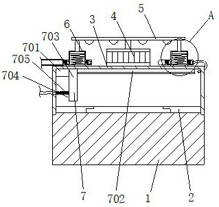
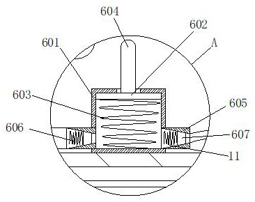
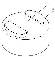
[0038] Example 1: Please refer to Figure 1-3 , the present invention proposes circuit board production equipment based on vacuum etching technology, including a base 1, a pallet 2, an etching cylinder 3, a rotating motor 4, a turntable 5, a vacuum device 6 and an etching device 7, and the base 1 and the etching cylinder 3 are all in the form of Cylinder and matching size, the bottom surface of the etching cylinder 3 is hollowed out, the clamping plate 2 is an inverted L-shaped body, the number of the clamping plates 2 is two and is opposite to the left and right, and the sides of the two clamping plates 2 facing away from each other are in the shape of Curved and compatible with the inner wall of the etching cylinder 3, the etching cylinder 3 is sleeved on the outer walls of the two clamping plates 2, the rotating motor 4 is fixedly installed on the top surface of the etching cylinder 3, the transmission shaft of the rotating motor 4 is fixedly connected with the turntable 5, ...

Embodiment 2

[0040] Example 2: Please refer to Figure 4-5 On the basis of Embodiment 1, the left side of the etching nozzle 703 is fixedly connected with a cleaning cylinder 704, the bottom surface of the cleaning cylinder 704 is hollowed out and the outer wall is provided with holes, the left side of the cleaning cylinder 704 is fixedly connected and communicated with a bellows 705, The left end of the corrugated pipe 705 on the cleaning cylinder 704 is fixedly connected with the inner wall on the left side of the etching cylinder 3, and the outer wall on the left side of the etching cylinder 3 is fixedly connected to the position of the corrugated pipe 705 on the cleaning cylinder 704 and is connected with a trachea. The right side air guiding column 605 on the side vacuum device 6 is fixedly connected and communicated, the left side air guiding column 605 on the left side vacuum device 6 is fixedly connected with a recovery pipe, and the right side air guiding column 605 on the left sid...

Embodiment 3

[0041] Embodiment 3: Please refer to Figure 6-8. On the basis of Embodiment 1, a reset mechanism 9 is provided on the right side of the etching cylinder 3. The reset mechanism 9 includes a bottom rod 901 and an insertion rod 902. The top surface of the bottom rod 901 is Holes are opened and socketed with the insertion rod 902, the bottom rod 901 is fixedly connected with the base 1, the insertion rod 902 is fixedly connected with the etching cylinder 3, the front of the insertion rod 902 is fixedly connected with a sector plate 903, and the front of the bottom rod 901 is fixedly connected with a cylinder C904, the inside of the cylinder C904 is hollow and there are round holes on the front and right sides, the inner wall of the back of the cylinder C904 is fixedly connected with the central axis 905, the outer wall of the central axis 905 is fixedly connected with the sleeve 906, and the outer wall of the sleeve 906 is located in the cylinder Outside C904, the outer wall of the...


PUM


Abstract

The invention relates to the field of etching technology, and discloses circuit board production equipment based on vacuum etching technology, which includes a base, a clamping plate, an etching cylinder, a rotating motor, a turntable, a vacuum device and an etching device. The bottom surface of the etching cylinder is in a hollow state, and the clamping plate It is an inverted L-shaped body. The number of clamping plates is two and they are opposite to each other. The side of the two clamping plates facing away from each other is curved and matches the inner wall of the etching barrel. The vacuum device and the etching device are both installed on the etching barrel. , through the setting of the vacuum device, the continuous air extraction effect is used to form a vacuum effect in all the bases, so as to perform a strong extraction effect on the dust in the base, thereby removing the dust in the base or circuit board before etching, and etching The smoke and impurities generated by the chemical reaction during the process increase the cleanliness of the circuit board after the etching is completed, and avoid the problem of reduced quality of the circuit board caused by dust and other smoke and impurities participating in the etching process. Compared with the cleaning mechanism on the existing etching machine , the cleaning scope is more comprehensive and the intensity is stronger.

Description

technical field [0001] The invention relates to the technical field of etching, in particular to circuit board production equipment based on vacuum etching technology. Background technique [0002] Existing etching machines for circuit boards mostly use the method of spraying chemical solutions to etch the exposed metal parts, so as to obtain the required geometric patterns and high-precision dimensions. [0003] The existing patent No. CN102092955A proposes an etching device, which has the advantage of reducing the occurrence of etching defects, but it lacks the effect of effectively cleaning the etching environment and impurities on the circuit board and effectively recovering the etching solution before and during etching. This leads to the reduction of the etching effect of the circuit board and the reduction of the efficiency of the front and rear processing. [0004] The existing patent No. CN103208438A proposes an etching device, which has the advantages of saving co...

Claims


Application Information

Patent Timeline
Patent Type & Authority Patents(China)
IPC IPC(8): H05K3/06
CPCH05K3/068
Inventor 高欢欢
Owner 东莞感恩蚀刻科技有限公司
Learn More