Curing device and drying equipment

A technology for curing devices and partitions, applied in lighting and heating equipment, drying, dryers, etc., can solve the problems of long curing time, large tiling area, and large area of ​​heating furnaces, reducing the need for Small contact area, scratch prevention, and reduced footprint

Inactive Publication Date: 2021-01-08
CFDR SHENZHEN TECH CO LTD
View PDF6 Cites 1 Cited by
  • Summary
  • Abstract
  • Description
  • Claims
  • Application Information

AI Technical Summary

Problems solved by technology

Due to the long time required for curing, in the related art, the electronic components are generally laid out in a heating furnace for curing. The furnace occupies a large area, which does not meet the needs of actual production

Method used


Image

  • Curing device and drying equipment
  • Curing device and drying equipment
  • Curing device and drying equipment

Examples


Embodiment Construction

[0030] The specific technical features in each embodiment described in the specific implementation modes can be combined in various ways if there is no contradiction. For example, different implementation modes can be formed by combining different specific technical features. Necessary repetition, various possible combinations of specific technical features in the present invention will not be further described.

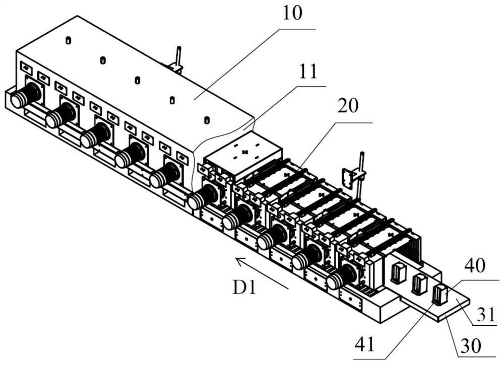
[0031] In a specific embodiment, the curing device provided by the present invention is used to cure the printed circuit on the electronic component, and the electronic component can be a silicon chip in any electronic system that needs to use a printed circuit, for example, it can be a silicon chip of a server chip, or It could be a silicon chip in a motor controller, or it could be a silicon chip in a solar cell. Those skilled in the art should know that the specific application field of the curing device and the type of specific cured electronic components do not ...


PUM


Abstract

The invention provides a curing device and drying equipment. The curing device comprises a shell, wherein a hollow heating cavity is formed in the shell, a heating assembly, wherein the heating assembly is arranged in the heating cavity, a conveying assembly, wherein the conveying assembly penetrates through the heating cavity in a first direction, and a conveying surface of the conveying assemblycan move in the first direction, and a containing piece, wherein the containing piece forms a hollow containing cavity, a plurality of partition pieces which are distributed at intervals in a seconddirection are arranged on the wall surface, adjacent to the containing cavity, of the containing piece, the second direction is basically perpendicular to the first direction, one end of each partition piece is connected with the wall surface, and the other end, opposite to the above-mentioned end, of each partition piece is a free end, and the containing piece is arranged on the conveying surfaceof the conveying assembly and moves in the first direction along with the conveying assembly. According to the curing device and the drying equipment, the corresponding occupied area can be effectively reduced.

Description

technical field [0001] The invention relates to the field of electronic component processing, in particular to a curing device. Background technique [0002] During the processing of electronic components with printed circuits, after the circuit is printed on the surface of the electronic component, the electronic component needs to be dried to volatilize the organic substances contained in the paste on the surface of the electronic component, so that the surface of the electronic component after printing is metallic The electrodes are brought into contact with the substrate of the electronic component (such as a silicon wafer) to form solidified metal electrodes. Due to the long time required for curing, in the related art, the electronic components are generally laid out in a heating furnace for curing. The furnace occupies a large area, which does not meet the needs of actual production. Contents of the invention [0003] The invention provides a curing device and dry...

Claims


Application Information

Patent Timeline
Patent Type & Authority Applications(China)
IPC IPC(8): F26B15/14F26B21/00F26B21/02F26B25/00F26B25/02F26B25/18F25D31/00
CPCF25D31/00F26B15/14F26B21/001F26B21/004F26B21/02F26B25/003F26B25/02F26B25/18
Inventor 谢建刘永才杨凡
Owner CFDR SHENZHEN TECH CO LTD
Why Eureka
Try Eureka