A ductile composite bridge deck composed of T-section steel

A T-section steel and composite bridge technology, applied in bridges, bridge parts, bridge construction, etc., can solve problems such as affecting the corrosion resistance and durability of bridge decks, increasing bridge structural repair and maintenance costs, and affecting structural fatigue performance. Avoid binding steel mesh, improve out-of-plane stability, and improve construction efficiency

Active Publication Date: 2022-07-05
ZHEJIANG UNIV
View PDF9 Cites 0 Cited by
  • Summary
  • Abstract
  • Description
  • Claims
  • Application Information

AI Technical Summary

Problems solved by technology

However, there are still some problems in the existing steel-concrete composite bridge deck: First, in order to ensure the sufficient shear connection between steel and concrete and prevent the detachment of the two interfaces, more bolts are usually arranged between the two Nails (playing the dual role of shear resistance and pull resistance), which greatly increases the construction workload, and the fatigue performance of the structure is affected due to the existence of welds; second, the steel deck part of the composite bridge deck usually needs to be welded out of the plane Multiple stiffeners, which also increase the amount of construction and affect the fatigue performance of the structure; third, ordinary concrete materials are prone to cracking under tension, and are sensitive to local defects, and are prone to cracks under long-term loads, causing water and ion erosion, affecting The corrosion resistance and durability of the bridge deck will significantly increase the repair and maintenance costs of the bridge structure, causing a huge waste of manpower and material resources

Method used


Image

  • A ductile composite bridge deck composed of T-section steel
  • A ductile composite bridge deck composed of T-section steel
  • A ductile composite bridge deck composed of T-section steel

Examples


Embodiment Construction

[0033] Embodiments of the ductile composite bridge deck composed of T-section steel of the present invention will be described in detail below with reference to the accompanying drawings.

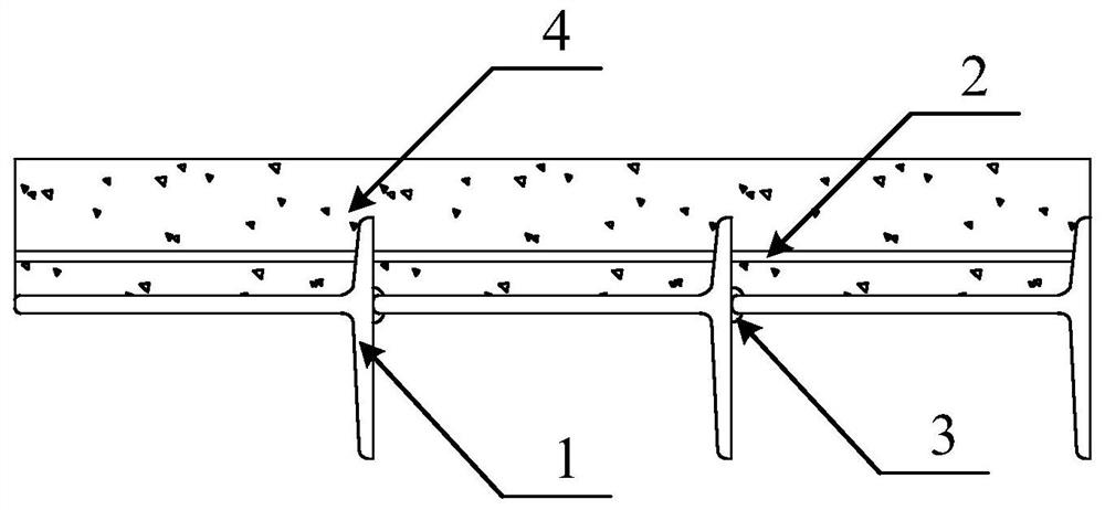
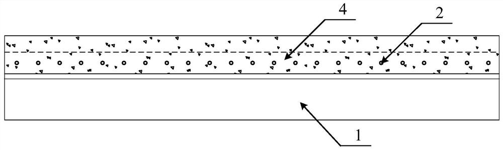
[0034] like figure 1 and figure 2 As shown, a ductile composite bridge deck composed of T-shaped steel includes the following components: hot-rolled T-shaped steel 1 , transverse reinforcement 2 , and ultra-high ductile concrete 4 .

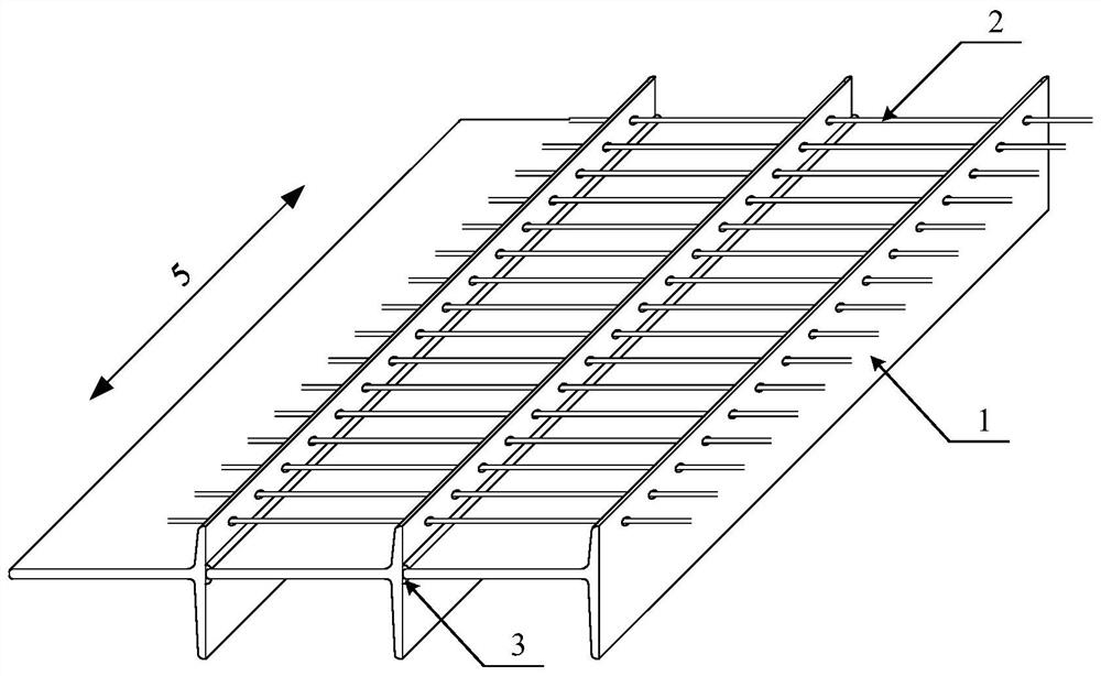
[0035] like image 3 As shown, the hot-rolled T-shaped steels 1 are continuously placed side by side in the transverse direction of the bridge deck, and the adjacent hot-rolled T-shaped steels 1 are welded by two fillet welds 3 to form a bridge deck steel frame. 5 is the longitudinal direction of the bridge deck.

[0036] like Figure 4 As shown, the lower flange of the hot-rolled T-section steel 1 is longer, which acts as an external stiffening effect on the plate surface; the upper flange of the hot-rolled T-section steel 1 is shorter and has a row of r...


PUM

PropertyMeasurementUnit
lengthaaaaaaaaaa
diameteraaaaaaaaaa
elastic modulusaaaaaaaaaa

Abstract

The invention discloses a toughness composite bridge deck system composed of T-shaped steel, including hot-rolled T-shaped steel, transverse steel bars and ultra-high toughness concrete. The T-section steels are continuously placed side by side along the bridge deck, and the adjacent section steels are welded by two fillet welds to form the bridge deck steel skeleton. The lower flange of the T-shaped steel is longer, which acts as an external stiffening effect on the plate surface; the upper flange of the hot-rolled T-shaped steel is shorter and has a row of circular holes, and the transverse steel bars pass through each T-shaped steel flange through the circular holes. The ultra-high toughness concrete is poured on the bridge deck steel frame to protect the bridge deck steel frame. In the composite bridge deck system proposed by the present invention, the ultra-high toughness concrete can ensure that no or only tiny cracks below 100 microns are generated, and the toughness and durability of the structure are improved; It also improves the out-of-plane stability of the bridge deck, significantly reduces material costs and construction complexity, and has superior fatigue performance.

Description

technical field [0001] The invention relates to the technical field of structural engineering, in particular to a ductile composite bridge deck composed of T-shaped steel. Background technique [0002] With the continuous advancement of infrastructure construction in our country, people realize that the convenience of intra-city and inter-city transportation greatly affects the development of the national economy and social progress; therefore, the country has achieved great development of road and bridge engineering in recent decades. . Among them, bridge structures are not only widely used in urban overpasses, subway light rails, high-speed railways, etc., but also in cross-river and sea-crossing structures. In recent years, with the construction of super-large bridge projects such as the Hong Kong-Zhuhai-Macao Bridge and the Hangzhou Bay Bridge, bridge structures at home and abroad are facing unprecedented development opportunities. In the construction of the bridge str...

Claims


Application Information

Patent Timeline
Patent Type & Authority Patents(China)
IPC IPC(8): E01D19/12C04B28/02E01D101/26C04B111/34
CPCE01D19/125C04B28/02E01D2101/26C04B2111/343C04B2201/50C04B18/08C04B18/146C04B18/141C04B14/106C04B16/0641C04B16/0625C04B16/0691Y02W30/91
Inventor 童精中李庆华徐世烺
Owner ZHEJIANG UNIV
Why Eureka
Try Eureka