A novel environment-friendly heating system and method

A heating system, environmental protection technology, applied in the field of new environmental protection heating system, can solve the problems of easy freezing of water, limited coal, troubles, etc.

Active Publication Date: 2022-06-07
SHANDONG HUAYU UNIV OF TECH
View PDF8 Cites 0 Cited by
  • Summary
  • Abstract
  • Description
  • Claims
  • Application Information

AI Technical Summary

Problems solved by technology

However, the coal of the existing coal-fired stove is limited at one time. When people are watching during the day, they can regularly add coal lumps. Door closed to allow coal to burn slowly for heating
In this case, if the coal burning speed is very low, it can ensure burning overnight, but the heating effect on the circulating water is poor, and the indoor temperature is low; if the coal burning speed is high, it is difficult to ensure burning overnight, the second It needs to be ignited again in the early morning, which is troublesome, and the indoor temperature is very low in the early morning of the next day, and people's normal activities are limited
In addition, there is a lot of ash in the flue gas of the existing coal-fired furnace. Generally, the flue gas is directly led to the outdoor discharge through the chimney, resulting in waste of heat, and the ash carried by it is easy to pollute the outdoor environment.
[0005] Solar thermal collectors are widely used in rural areas, but most of them are limited to spring, summer and autumn. In winter, the water in solar thermal collectors is easy to freeze and it is difficult to continue to use them, making it difficult to obtain this kind of clean energy.

Method used


Image

  • A novel environment-friendly heating system and method
  • A novel environment-friendly heating system and method
  • A novel environment-friendly heating system and method

Examples


Embodiment

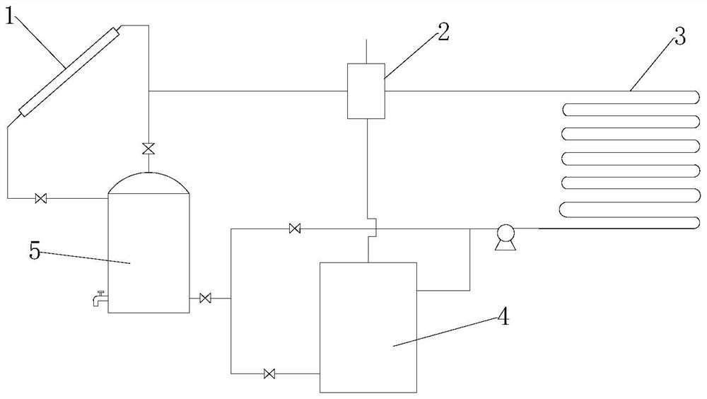
[0081] like figure 1 As shown, a new type of environment-friendly heating system includes:

[0082] solar collector 1;

[0083] The outer wall of the water storage tank 5 is provided with a thermal insulation structure, the outlet of the solar collector 1 is connected to the top of the water storage tank 5, and the bottom outlet of the water storage tank 5 is connected to the radiator inlet through a pump;

[0084] The coal-fired furnace 4 is provided with a circulating water pipeline on the outside of the combustion chamber, the inlet of the circulating water pipeline is connected with the bottom outlet of the water storage tank 5, and the outlet of the circulating water pipeline is connected with the inlet of the radiator 3 through a pump;

[0085] The outlet of the radiator 3 is connected to the inlet of the water channel of the heat exchanger 2, the outlet of the flue gas of the coal-fired furnace 4 is connected to the inlet of the flue gas channel of the heat exchanger, ...


PUM


Abstract

The invention discloses a novel environment-friendly heating system and method, comprising: a solar heat collector; a water storage tank, the outer wall of which is provided with a thermal insulation structure; The outlet is connected to the inlet of the radiator through a pump; the coal-fired furnace has a circulating water pipeline on the outside of the combustion chamber, the inlet of the circulating water pipeline is connected to the bottom outlet of the water storage tank, and the outlet of the circulating water pipeline is connected to the inlet of the radiator through a pump; the radiator The outlet is connected to the inlet of the water channel of the heat exchanger, the flue gas outlet of the coal-fired furnace is connected to the inlet of the flue gas channel of the heat exchanger, and the water channel exchanges heat with the partition wall of the flue gas channel; the outlet of the water channel of the heat exchanger passes through the three-way respectively It is connected with the inlet of the solar collector and the top of the water storage tank; a valve is set on the connecting pipeline, and the top of the water storage tank is lower than the solar collector, and the height difference is greater than 1m.

Description

technical field [0001] The invention belongs to the technical field of heating, and in particular relates to a novel environment-friendly heating system and method. Background technique [0002] The information disclosed in this Background section is only for enhancement of understanding of the general background of the invention and should not necessarily be taken as an acknowledgement or any form of suggestion that this information forms the prior art already known to a person of ordinary skill in the art. [0003] With the rapid development of the national economy, people have higher and higher requirements for the quality of life. For the vast rural areas, heating in winter is also more important. At present, many rural areas do not have heating. Among the households with heating, the heating is relatively scattered, and the heating forms are different, such as air source heat pump, heating furnace, electric heating, kang, fire wall and so on. The efficiency of air sour...

Claims


Application Information

Patent Timeline
Patent Type & Authority Patents(China)
IPC IPC(8): F24D12/02F24D19/00
CPCF24D12/02F24D19/0095F24D19/00F24D2200/14F24D2200/062F24D2200/32Y02B30/00
Inventor 刘春花刘忠梅
Owner SHANDONG HUAYU UNIV OF TECH
Why Eureka
Try Eureka