
Eddy current crank arm buffer

A buffer and articulating arm technology, applied in the field of buffers, can solve the problems of unsuitable industrial buffers, achieve obvious buffering effects, reduce downtime and maximize economic benefits

Active Publication Date: 2022-04-29
湖南省潇振工程科技有限公司
View PDF8 Cites 0 Cited by
  • Summary
  • Abstract
  • Description
  • Claims
  • Application Information

AI Technical Summary

Problems solved by technology

[0005] Considering the structure of the above electromagnetic damper and the damping strength it can provide, it is not suitable for some industrial buffers

Method used


Image

  • Eddy current crank arm buffer
  • Eddy current crank arm buffer
  • Eddy current crank arm buffer

Examples


Embodiment Construction

[0029] The present invention will be further described in detail below in conjunction with examples and specific implementation methods. However, it should not be understood that the scope of the above subject matter of the present invention is limited to the following embodiments, and all technologies realized based on the content of the present invention belong to the scope of the present invention.

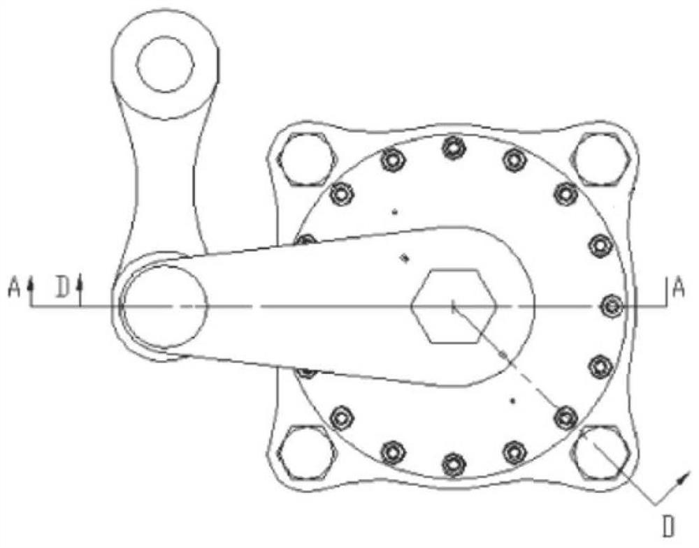
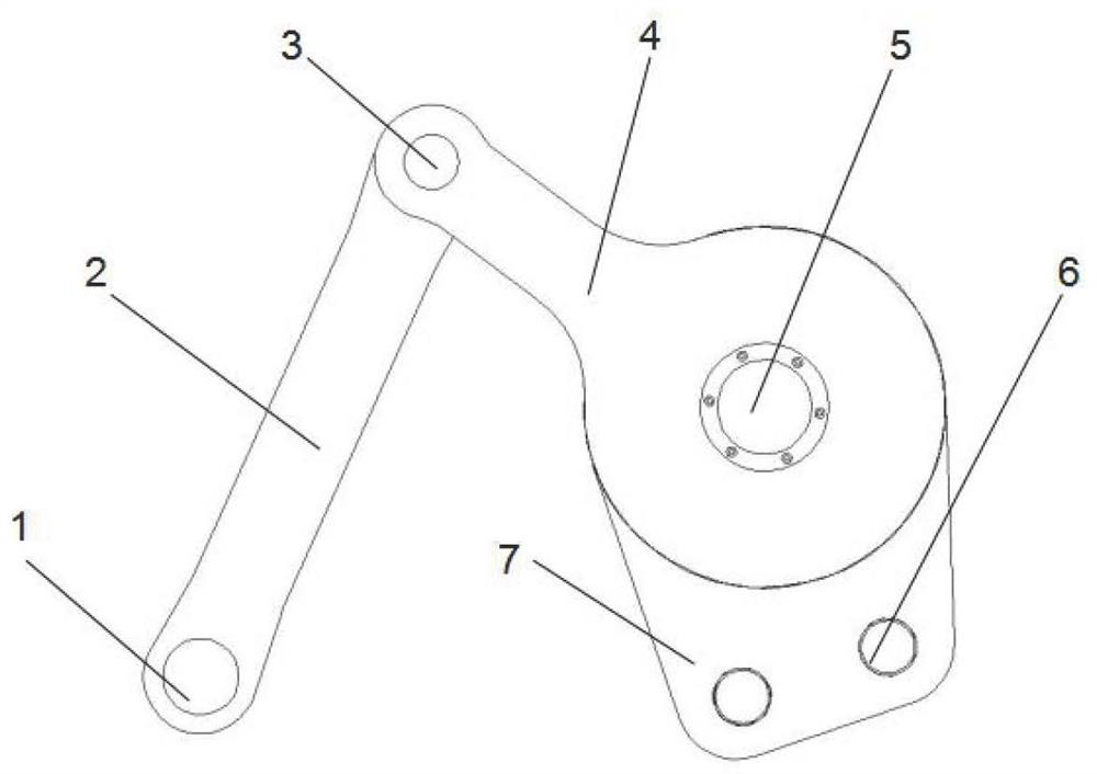
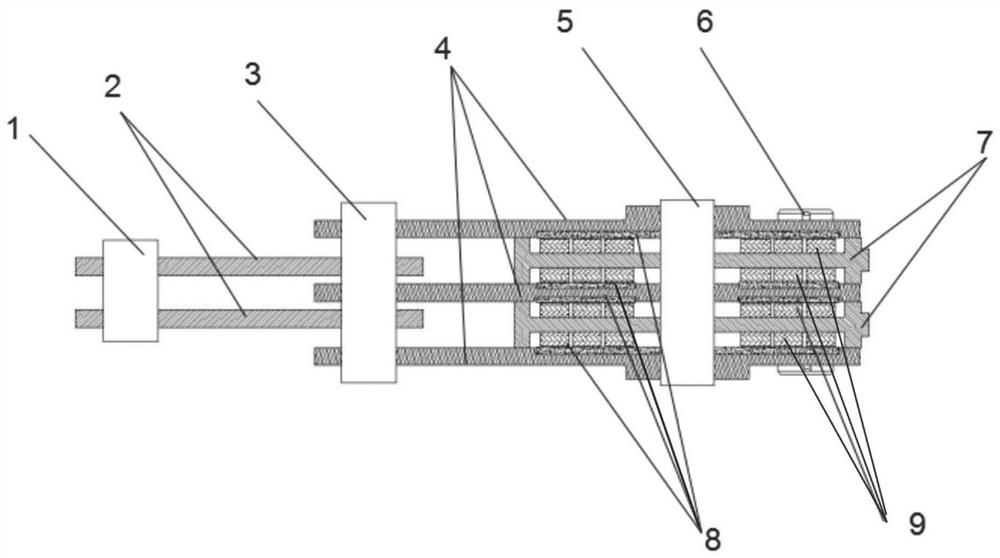
[0030] Specific embodiments of the present invention, such as figure 2 and image 3 As shown, an electric eddy current crank arm buffer is mainly composed of two main parts including a transmission support assembly and an electric eddy current buffer generator, wherein the transmission support assembly includes a pin shaft 1, a connecting rod 2, a pin shaft 3, and a rocker arm 4. The magnetic steel support plate 7 and the fixed shaft 5, wherein the rocker arm 4 is composed of 3 plates, the magnetic steel support plate 7 is composed of 2 plates, and the rocker arm 4 and the ma...


PUM


Abstract

The invention discloses an electric eddy current crank arm buffer, which includes a rocker arm, and a connecting rod is hinged on the rocker arm. A fixed fixed part, the support plate can rotate with the rocker arm about the shaft or axis, a magnet and a conductor, one of the magnet and the conductor is installed on the support plate, and the other of the magnet and the conductor is installed on the On the rocker arm, and the position of the magnet and the conductor is opposite, the rotation of the support plate and the rocker arm about the shaft or the axis can drive the magnet and the conductor to cut the magnetic force line to generate a damping force. The buffer of the invention has a simple and durable structure, obvious buffering effect, no working fluid, no liquid leakage problem, and no power supply for working in a magnetic field. Especially when applied to an electric shovel, it can reduce the maintenance cost of the electric shovel, reduce the failure time of the electric shovel, and create greater economic benefits for mine production.

Description

technical field [0001] The invention relates to the technical field of buffers, in particular to a crank arm type buffer utilizing the eddy current effect. Background technique [0002] Shock absorbers are often used to reduce the impact force caused by vibration between various components. Traditional buffer devices include mechanical and hydraulic. The mechanical buffer needs to adjust the preload of the spring frequently. If it is not adjusted properly, the buffer will be too tight or too loose; while the hydraulic buffer has problems of leakage and sealing. These two types of buffers have high requirements on the structure and materials in contact with each other, and the fatigue strength and durability of the structures and materials are often difficult to meet the requirements, resulting in poor buffering effect of the buffer device and low service life. and high replacement costs. [0003] When the above-mentioned mechanical or hydraulic buffer device is applied to...

Claims


Application Information

Patent Timeline
Patent Type & Authority Patents(China)
IPC IPC(8): F16F15/18
CPCF16F15/18
Inventor 陈谨林黄劲张弘毅牛华伟陈政清
Owner 湖南省潇振工程科技有限公司
Learn More