
Multi-treatment-terminal radiotherapy device

A radiation therapy and terminal technology, which is applied in the field of multi-treatment terminal radiation therapy devices, can solve problems such as the inability to provide long pulse X-rays, and achieve the effect of improving beam utilization efficiency

Pending Publication Date: 2021-01-01
中玖闪光医疗科技有限公司
View PDF0 Cites 4 Cited by
  • Summary
  • Abstract
  • Description
  • Claims
  • Application Information

AI Technical Summary

Problems solved by technology

At present, the radiation dose rate of medical accelerators is about 0.1Gy / s, and the total radiation for tumor patients is about 7.5 hours, which is distributed in 1.5 months. The existing radiation therapy devices based on medical normal-temperature linear accelerators cannot provide long-pulse and high-dose rate X-rays.

Method used


Image

  • Multi-treatment-terminal radiotherapy device
  • Multi-treatment-terminal radiotherapy device
  • Multi-treatment-terminal radiotherapy device

Examples


Embodiment 1

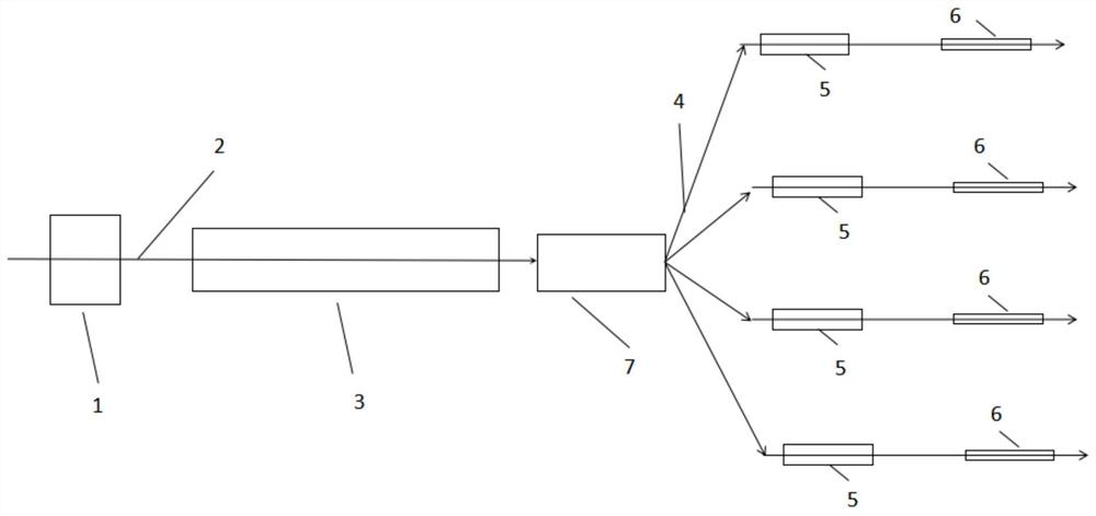
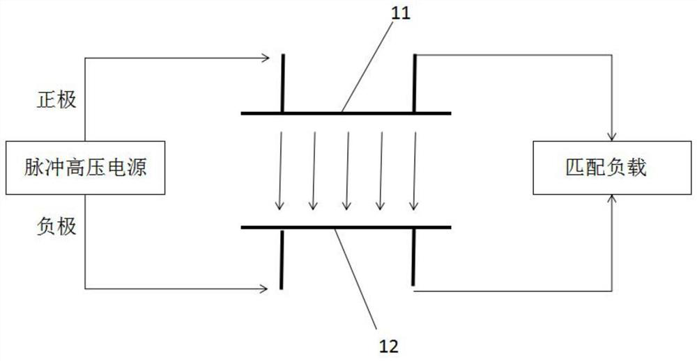
[0043] Such as figure 1As shown, a multi-treatment terminal radiotherapy device includes an electron source 1, a radio frequency superconducting linear accelerator 3, a beam splitting assembly 7, an X-ray target 5 and an X-ray collimator 6 in sequence, wherein the electron source 1 is used to generate The long-pulse low-energy electron beam forms a pulse train, and the long-pulse low-energy electron beam is transmitted to the radio-frequency superconducting linear accelerator 3 through the first beam transmission line 2, and the radio-frequency superconducting linear accelerator 3 is used to perform energy gain on the long-pulse low-energy electron beam to obtain Long-pulse high-energy electron beams, and multiple long-pulse high-energy electron beams in the pulse train have the same transmission direction, and the beam splitting component 7 is used to apply different forces to the multiple long-pulse high-energy electron beams in the pulse train with the same transmission dire...

Embodiment 2

[0057] The same part of this embodiment and Embodiment 1 will not be described again, the difference is:

[0058] The electron source 1 adopts a DC high-voltage electron gun. The DC high-voltage electron gun generates a long-pulse low-energy electron beam BE1 with an energy of about 300kV. The low-energy electron beam and the driving laser have the same time distribution, less than 10 ps.

[0059] The radio frequency resonant cavity uses two 4-unit TESLA cavity types at 1.3GHz, the field gradient adjustment range is 0-10MV / m, the effective acceleration length is 1m, the electron beam energy gain adjustment range is 0-10MeV, and the long-pulse high-energy electron beam energy is 6~8MeV.

[0060] The X-ray target 5 is a tungsten target and is a rotating target, that is, the X-ray target 5 continuously rotates to impel the deflected electron beams to hit different parts, so as to avoid burning the X-ray target 5 due to excessive heat concentration. In some other embodiments, wa...


PUM


Abstract

The invention relates to a multi-treatment-terminal radiotherapy device, and belongs to the technical field of radiotherapy. The multi-treatment-terminal radiotherapy device sequentially comprises anelectron source, a radio frequency superconducting linear accelerator, a beam splitting assembly, X-ray targets and X-ray collimators. According to the multi-treatment-terminal radiotherapy device, the electron source and the radio frequency superconducting linear accelerator are adopted to provide long-pulse high-dose-rate X-rays, a very high irradiation dose can be given to treatment terminals in a short time, the energy of the X-rays can be adjusted by adjusting the energy of electron beams, the time length of the X-rays can be adjusted by adjusting the pulse length of the electron beams, and the dose rate can be adjusted by adjusting the flow intensity of the electron beams so that a better radiotherapy effect of the treatment terminals can be achieved; and in addition, the beam splitting assembly is adopted, and beams of the radio frequency superconducting linear accelerator are distributed to different treatment terminals, so that the beam utilization efficiency and the radiotherapy efficiency are improved.

Description

technical field [0001] The invention belongs to the technical field of radiotherapy, and in particular relates to a multi-treatment terminal radiotherapy device. Background technique [0002] At present, the incidence of tumors in our country is getting higher and higher, and tumors have become one of the biggest killers that endanger national health. Common methods of anti-tumor treatment include surgery, radiotherapy, and chemotherapy. The principle of radiation therapy is to act on the cells through a certain amount of energy rays, and finally destroy the DNA double strands of tumor cells through direct or indirect effects, so as to inhibit the proliferation of tumor cells and directly kill tumor cells. While receiving a sufficient lethal dose, the organs at risk are protected from radiation damage to the greatest extent possible. Under the current conditions of radiotherapy, by improving the conformity of the radiation field of the radiotherapy machine, the tumor tissue...

Claims


Application Information

Patent Timeline
Patent Type & Authority Applications(China)
IPC IPC(8): A61N5/10
CPCA61N5/103A61N5/1042A61N5/1048A61N5/1077A61N2005/1089A61N2005/1092
Inventor 黎明吴岱王建新杨兴繁李鹏肖德鑫赵剑衡陈门雪单李军沈旭明和天慧胡栋材徐勇周奎王汉斌劳成龙罗星白燕闫陇刚陈立均刘宇刘婕周征张德敏潘清柏伟陈亚男邓仕钰李文君宋志大
Owner 中玖闪光医疗科技有限公司
Learn More