
Textile drying device with ironing function and using method

A drying device and technology for textiles, applied in the direction of textiles and papermaking, drying, drying machines, etc., can solve the problems of reducing the running speed of textiles, low ironing and drying efficiency, and different temperature requirements, so as to improve ironing and drying. Drying efficiency, scientific overall structure layout, and large contact area

Inactive Publication Date: 2020-12-29
安徽职业技术学院
View PDF7 Cites 3 Cited by
  • Summary
  • Abstract
  • Description
  • Claims
  • Application Information

AI Technical Summary

Problems solved by technology

[0004] However, there are deficiencies in this textile automatic ironing cylinder device. The first is that the contact area between the ironing cylinder group and the textile is less. In order to ensure the ironing effect, the contact time can only be increased, that is, the running speed of the textile is reduced, which makes The overall ironing and drying efficiency is relatively low; the second is that different textiles have different temperature requirements for ironing, and the ironing drum device is not convenient for temperature adjustment

Method used


Image

  • Textile drying device with ironing function and using method
  • Textile drying device with ironing function and using method
  • Textile drying device with ironing function and using method

Examples


Embodiment Construction

[0030] The following will clearly and completely describe the technical solutions in the embodiments of the present invention with reference to the accompanying drawings in the embodiments of the present invention. Obviously, the described embodiments are only some, not all, embodiments of the present invention. Based on the embodiments of the present invention, all other embodiments obtained by persons of ordinary skill in the art without creative efforts fall within the protection scope of the present invention.

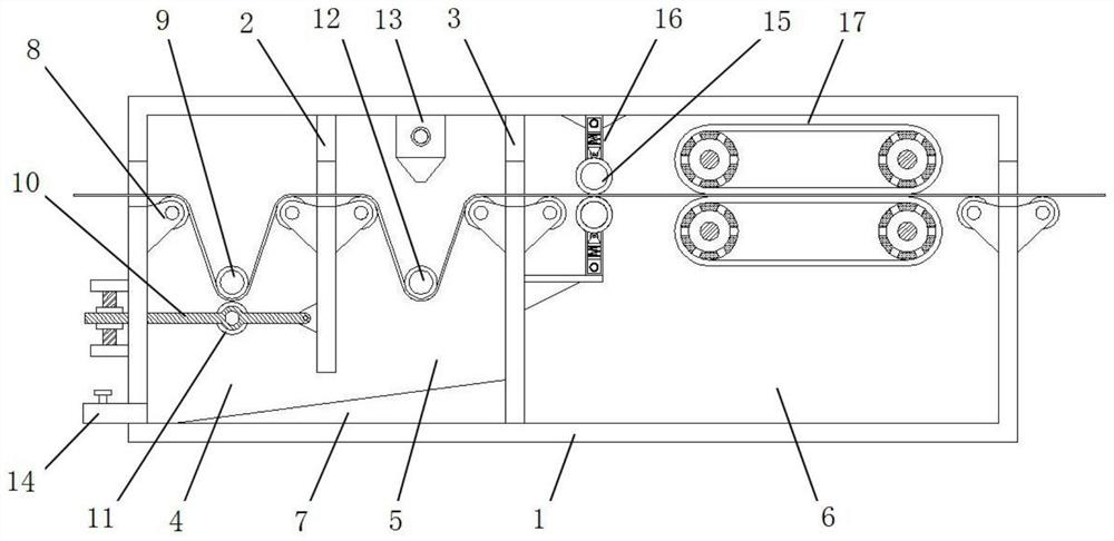
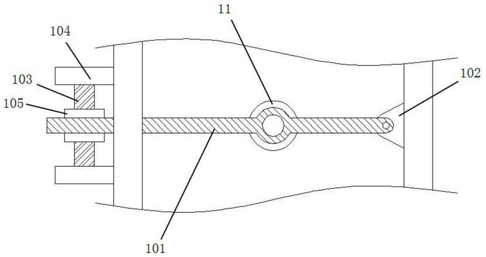
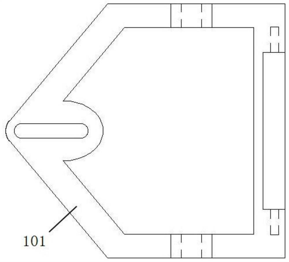
[0031] see Figure 1-5 As shown, this embodiment is a textile drying device with ironing function, including a drying box 1, the drying box 1 is in the shape of a cuboid as a whole, and its inner cavity is surrounded by a first partition 2 and a second partition 3 It is divided into draining room 4, pre-drying room 5 and ironing room 6. The front and rear end plates of the drying box 1 and the first dividing plate 2 and the second dividing plate 3 are provided wit...


PUM

PropertyMeasurementUnit
Lengthaaaaaaaaaa

Abstract

The invention discloses a textile drying device with an ironing function and a using method thereof.The textile drying device comprises a drying box, an inner cavity of the drying box is divided intoa draining chamber, a pre-drying chamber and an ironing chamber through a first partition plate and a second partition plate, an upper pressing roller is rotationally supported between two supportingrollers in the draining chamber, a lower pressing roller is rotationally supported in the draining chamber through an adjusting frame assembly, a guide roller is rotationally supported in the pre-drying chamber, and an air knife is fixed to the top wall of the pre-drying chamber; and pretreatment rollers are symmetrically arranged on the front portion of the ironing chamber and abut against a cleaning cylinder assembly, and ironing assemblies are symmetrically arranged on the rear portion of the ironing chamber. The textile drying device is reasonable in structural design, textiles can be sequentially moved into the draining chamber to be drained, moved into the pre-drying chamber to be pre-air-dried, moved to the pretreatment rollers of the ironing chamber to be subjected to impurity removal and flattening and then moved to the ironing assemblies of the ironing chamber to be ironed under the traction effect, ironing is achieved through gathering in the drying process, and subsequent process flow is simplified.

Description

technical field [0001] The invention relates to the technical field of textile production, in particular to a textile drying device with an ironing function and a use method. Background technique [0002] In the process of production, processing, and placement of textiles, moving back and forth, processing, etc., it is necessary to treat the fabric in advance after thermal processing, which will produce a certain shrinkage, and by the way, use the ironing device to remove the wrinkles on the fabric. Ironing ensures the quality of subsequent clothing tailoring. If these wrinkles cannot be removed, it will affect the color and smoothness of the textile, thereby reducing the quality of the textile and affecting its subsequent sales. In the prior art, most of the textiles are ironed manually, which is labor-intensive, and the high temperature of the ironing device is likely to cause injuries to workers, which is not conducive to mass production, and mechanized ironing cannot gua...

Claims


Application Information

Patent Timeline
IPC IPC(8): F26B13/00F26B13/28F26B13/10F26B21/00F26B25/00F26B7/00D06C15/02
CPCD06C15/02F26B7/00F26B13/00F26B13/10F26B13/28F26B21/004F26B25/003
Inventor 倪中秀
Owner 安徽职业技术学院
Learn More