Electric heating furnace

An electric heating furnace and furnace body technology, applied in the field of electric heating furnaces, can solve the problems of single cooling fan function, hot furnace shell, large heat loss, etc., to improve the safety and stability of use, and the flow of wind is smooth and accurate. , the effect of reducing the surface temperature

Active Publication Date: 2020-12-29
佛山市顺德区普发特电器实业有限公司
View PDF10 Cites 1 Cited by
  • Summary
  • Abstract
  • Description
  • Claims
  • Application Information

AI Technical Summary

Problems solved by technology

[0009] The object of the present invention is to provide an electric heating furnace to overcome the single function of the heat dissipation fan in the prior art, the poor heat dissipation effect, the high temperature of the furnace body, the risk of scalding, the large heat loss, the low heating efficiency and the utilization of heat energy. Low efficiency, avoiding the disadvantages of heating the furnace shell; and the disadvantage of constant cooling fan speed, unable to achieve a balance of heat dissipation and heat utilization

Method used


Image

  • Electric heating furnace
  • Electric heating furnace
  • Electric heating furnace

Examples


no. 1 example

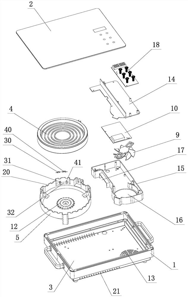
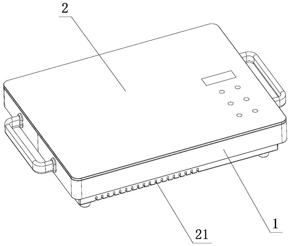
[0067] see Figure 1-Figure 6 , the electric furnace includes a furnace body 1, and a panel 2 and a bottom plate 3 respectively arranged on the upper and lower positions of the furnace body 1, and a heating element 4 and a heat recovery cover 5 are arranged in the furnace body 1; the heating element 4 is located on the panel 2 Below; the top of the heat recovery cover 5 is provided with an opening, and a heat insulating cavity 7 is formed to cover the periphery of the heating element 4; the heat recovery cover 5, the furnace body 1 and the bottom plate 3 form a wind flow channel, The wind flow channel communicates with the heat insulation cavity 7, and a cooling fan 9 and a main control board 10 are arranged therein.

[0068] The heat dissipation fan 9 draws the wind outside the furnace body 1 into the air flow channel, and first dissipates heat to the main control board 10, and then introduces it into the heat insulation chamber 7, takes away the heat leaked from the heating ...

no. 2 example

[0109] see Figure 7 , this electric furnace, it is different from the first embodiment in that:

[0110]The bottom plate 3 is provided with several air exhaust holes 21, these several air exhaust holes 21 are arranged on one side of the bottom plate 3, and the air induction hole 13 is arranged on the other side of the bottom plate 3, and forms a certain distance with the air exhaust holes 21 .

[0111] The wind in the heat insulation cavity 7 is exhausted outside the furnace body 1 through the cooperation of the air outlet 20, the cooling cavity 19, and the exhaust hole 21 in order to realize the single-bottom exhaust of the electric furnace.

[0112] Among them, the flow process of wind is as Figure 7 indicated by the arrow.

[0113] Others are not described in the first embodiment.

no. 3 example

[0115] see Figure 8 , this electric furnace, it is different from the first embodiment in that:

[0116] The side of the furnace body 1 is provided with several exhaust holes 21, and these several exhaust holes 21 are arranged at the upper position, or the middle position, or the lower position of the side portion of the furnace body 1, and the air induction hole 13 is arranged at the side of the bottom plate 3 , and form a certain distance with the exhaust hole 21 .

[0117] The wind in the heat insulation cavity 7 is exhausted outside the furnace body 1 through the cooperation of the air outlet hole 20, the cooling cavity 19, and the exhaust hole 21 in order to realize the unilateral exhaust of the electric furnace.

[0118] Among them, the flow process of wind is as Figure 8 indicated by the arrow.

[0119] Others are not described in the first embodiment.


PUM


Abstract

The invention relates to an electric heating furnace. The electric heating furnace comprises a furnace body, a cooling fan, a main control panel, a panel and a bottom plate, wherein the panel and thebottom plate are arranged at the upper part and the lower part of the furnace body respectively; a heating piece and a heat energy recovery cover are arranged in the furnace body; the heating piece ispositioned below the panel; an opening is formed in the top of the heat energy recovery cover, and a heat insulation cavity is formed to cover the periphery of the heating piece; an air flowing channel is formed among the heat energy recovery cover, the furnace body and the bottom plate and communicates with the heat insulation cavity; and the cooling fan is used for pumping air outside the furnace body into the air flowing channel, then guiding the air into the heat insulation cavity, dissipating heat of the heating piece and guiding and transferring heat leaked outwards by the heating pieceto the panel. Through the improvement, the air flow direction can be more reasonable and more accurate, the influence of heat on all members except the panel is reduced, heat leaked and lost by a heating body can be transmitted to the panel to the maximum extent and acts on a heated body, heat loss is reduced, and the heat utilization efficiency is improved.

Description

technical field [0001] The invention relates to an electric furnace. Background technique [0002] The types of electric stoves on the market include electric ceramic stoves, induction cookers, etc. Conventional electric furnaces have panels and heating components arranged on the panels. When the heating components work, heat will leak and radiate into the main body of the electric furnace. Since the main body of the electric furnace is also equipped with electrical components such as circuit boards, the circuit boards are placed in the main body of the electric furnace. The working life will be shortened in a high-heat environment. Therefore, a cooling fan or a heat shield covering the heating element is usually installed in the electric furnace. [0003] For example, the Chinese Patent Document No. CN110056916A disclosed on July 26, 2019 a multi-functional household electric heating furnace, which includes a shell, the upper surface of which is provided with a heating are...

Claims


Application Information

Patent Timeline
IPC IPC(8): F24C7/08F24C7/06F24C15/00F24C15/08
CPCF24C7/081F24C7/062F24C15/006F24C15/00F24C15/08
Inventor 黎伟文
Owner 佛山市顺德区普发特电器实业有限公司
Why Eureka
Try Eureka