
Method for selectively pressing alloy soldering lug on substrate

An alloy solder tab, a selective technology, applied in electrical components, semiconductor/solid-state device manufacturing, circuits, etc., can solve the problems of position offset, easy deformation or cracking, and reduced welding quality, etc., to achieve simple and feasible operation. High performance, high reliability integration and packaging effect

Active Publication Date: 2020-12-25
SOUTHWEST CHINA RES INST OF ELECTRONICS EQUIP
View PDF15 Cites 1 Cited by
  • Summary
  • Abstract
  • Description
  • Claims
  • Application Information

AI Technical Summary

Problems solved by technology

However, the thickness of the alloy solder sheet is extremely thin, soft or hard and brittle, and it is easily deformed or broken during use. It is difficult to process and use the preformed solder sheet with large size or fine lines.
Moreover, the accuracy of the installation and positioning of the solder preform is poor, and the position is easily shifted due to disturbance during the welding process, which reduces the welding quality

Method used


Image

  • Method for selectively pressing alloy soldering lug on substrate
  • Method for selectively pressing alloy soldering lug on substrate
  • Method for selectively pressing alloy soldering lug on substrate

Examples


Embodiment Construction

[0024] The present invention will be further described below in conjunction with the accompanying drawings.

[0025] Chinese patent CN103028804A "A Method for Covering a Chip Seal Cover Plate with Preforms" discloses a method of tinning the surface of gold-tin soldering sheets to reflow soldering at a temperature lower than the melting point of the gold-tin alloy, and passing the gold-tin soldering sheets through A method in which molten tin is pre-coated on a gold-plated cover. This method has the following problems: (1) tin plating will change the composition ratio of gold-tin solder preforms, which affects welding reliability; (2) gold-tin solder chips are brittle and cannot be soldered with complex and fine patterns Electroplating and pre-coating of chips, the application range is limited.

[0026] Chinese patent CN1556544A "preparation method of hermetic packaging cover plate for integrated circuit" and Chinese patent CN104952808A "a kind of pre-set gold tin cover plate ...


PUM


Abstract

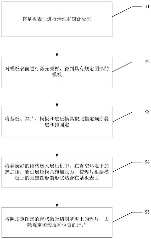
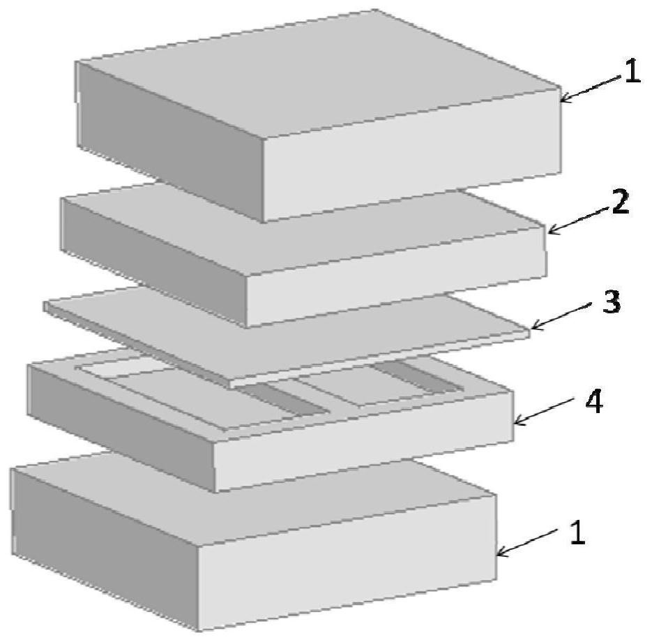
The invention relates to the field of microelectronic packaging, and discloses a method for selectively pressing an alloy soldering lug on a substrate, which comprises the following steps of: cleaningand plating the surface of the substrate; performing laser material reduction on the surface of the template to transfer the specified pattern to the template; laminating and pre-fixing the substrate, the soldering lug, the template and the laminating die according to a specified sequence; sending the laminated structure into a laminating machine, and heating and pressurizing in a vacuum environment, so that the soldering lug is attached to the substrate; and the soldering lugs on the substrate are cut through laser, and the soldering lugs corresponding to the specified patterns on the surface of the substrate are selectively reserved. According to the method, the alloy soldering lugs are selectively pressed on the surface of the substrate, high-quality and high-reliability integration and packaging between the chip, the module, the surrounding frame and the like and the substrate can be achieved, and the method has the advantages that the soldering lug size adjusting range is large,the line precision is high, alignment between the soldering lugs and the substrate is not needed, and disturbance displacement between the soldering lugs and the substrate is avoided.

Description

technical field [0001] The invention relates to the field of microelectronic packaging, in particular to a method for selectively pressing alloy welding sheets on a substrate. Background technique [0002] In microelectronic packaging, in order to achieve high-quality, highly reliable integration and packaging between chips, modules, frames, etc. Soldering to realize functions such as interconnection, fixing, heat dissipation or hermetic packaging. [0003] To precisely control the amount of solder and reduce solder overflow. Reduce unnecessary solder waste and reduce costs. Usually, the alloy solder sheet is punched into a specified shape according to the demand, that is, the preformed solder sheet. However, the thickness of the alloy solder sheet is extremely thin, soft or hard and brittle, and it is easily deformed or broken during use. It is difficult to process and use the preformed sheet with large size or fine lines. In addition, the installation and positioning a...

Claims


Application Information

Patent Timeline
Patent Type & Authority Applications(China)
IPC IPC(8): H01L21/48H01L21/768
CPCH01L21/4817H01L21/4882H01L21/76895H01L21/4871H01L21/4875
Inventor 吕英飞卢军杨宇
Owner SOUTHWEST CHINA RES INST OF ELECTRONICS EQUIP
Learn More