Gas stove

A gas stove and gas technology, applied in the field of gas stoves, can solve the problems of high emission concentration of NOx and CO, insufficient combustion of supporting gas, and high emission concentration, and achieve the effects of low emission of CO and NOx, stable flame and emission reduction.

Pending Publication Date: 2020-12-25
DALIAN INST OF CHEM PHYSICS CHINESE ACAD OF SCI
View PDF0 Cites 4 Cited by
  • Summary
  • Abstract
  • Description
  • Claims
  • Application Information

AI Technical Summary

Problems solved by technology

The traditional cooker is that the gas injects the primary air into the cooker structure and mixes it. After the premixed gas is ignited, it contacts with the secondary air through diffusion to complete the combustion process. Its structure is simple, the technology is mature, and the cost is low, but the thermal efficiency is low, and the emission concentration of CO and NOx High; the combustion plate of the infrared stove is a porous ceramic plate, and the gas is injected into the stove head to mix, and the ceramic plate is heated by flame combustion to turn into infrared combustion, but the ceramic is fragile, and the lack of gas is easy to burn insufficiently, the cost is high, and the thermal efficiency is high. , NOx and CO emission concentrations are high; there is nothing special about the stove head structure of the high-fire stove, which requires a relatively high gas pressure. Generally, the combustion-supporting air is injected and the fan provides combustion-supporting air. The structure is simple, the technology is mature, and the cost is low, but the thermal efficiency is low. , CO and NOx emission concentrations are high

Method used


Image

  • Gas stove
  • Gas stove
  • Gas stove

Examples


Embodiment Construction

[0025] In order to make the purpose, technical solutions and advantages of the embodiments of the present invention clearer, the technical solutions in the embodiments of the present invention will be clearly and completely described below in conjunction with the drawings in the embodiments of the present invention. Obviously, the described embodiments It is a part of embodiments of the present invention, but not all embodiments. Based on the embodiments of the present invention, all other embodiments obtained by persons of ordinary skill in the art without making creative efforts belong to the protection scope of the present invention.

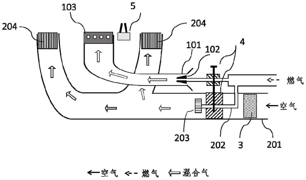
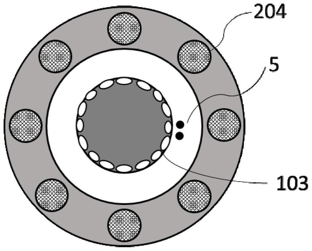
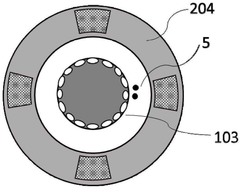
[0026] Such as figure 1 As shown, this embodiment discloses a gas stove, including a fan 3, an inner ring burner housing 101, an inner ring gas injection mechanism 102, an inner ring combustion head 103, an outer ring burner housing 201, and an outer ring gas burner housing. Pipe 202, outer ring gas distribution mechanism 203, outer ring com...


PUM


Abstract

The invention provides a gas stove. The gas stove comprises a draught fan, an inner ring burner housing, an outer ring burner housing, a gas distribution mechanism, an adjusting valve, burner heads and an igniter, wherein the gas distribution mechanism is used for distributing gas in the inner ring burner housing and the outer ring burner housing; an inner ring burner adopts gas injection type diffusion combustion; an outer ring burner adopts active air supply premixed combustion; the burner head of the outer ring burner comprises a main frame body and at least one stable burning isolation belt; the stable burning isolation belt divides the interior of the main frame body into at least two ventilation areas in the direction of a gas channel; a separation mechanism is arranged in each ventilation area and divides the ventilation area into a plurality of through holes distributed in the direction of the gas channel; the through holes are used for allowing premixed gas to pass through andstrengthening the mixing effect of the premixed gas and the through holes; and the stable burning isolation belt can divide burning flames on the burning face of the main frame body into mutually independent flames. According to the gas stove, the mixing degree of gas and air can be enhanced by the micropore structure, so that the burning is more sufficient, and the pollutants are few.

Description

technical field [0001] The invention relates to a gas stove. Background technique [0002] Gas stoves refer to kitchen utensils that are heated directly by gaseous fuels such as liquefied petroleum gas, artificial gas, and natural gas. The power of the gas stove is 3-5kW. After the pipe gas is injected into the air, it is ejected from the small holes set up on the inner plate and the outer ring. After ignition, the flame is divided into two layers: the gas and the injected air form a fuel-rich premix inside. Combustion flame; residual fuel and ambient air form a diffusion combustion flame externally. The traditional cooker is that the gas injects the primary air into the cooker structure and mixes it. After the premixed gas is ignited, it contacts with the secondary air through diffusion to complete the combustion process. Its structure is simple, the technology is mature, and the cost is low, but the thermal efficiency is low, and the emission concentration of CO and NOx ...

Claims


Application Information

Patent Timeline
Patent Type & Authority Applications(China)
IPC IPC(8): F24C3/08F23D14/04F23D14/58F23D14/62
CPCF23D14/04F23D14/58F23D14/62F23D2900/14062F24C3/085
Inventor 李为臻张景才张涛
Owner DALIAN INST OF CHEM PHYSICS CHINESE ACAD OF SCI
Why Eureka
Try Eureka