
High-pressure ion bombardment vacuum coating device and coating method thereof

A vacuum coating, high-voltage ion technology, applied in vacuum evaporation coating, ion implantation coating, sputtering coating and other directions, can solve the problems of surrounding workers' health effects, cumbersome wiring and maintenance, poor coating process, etc. Utilize the effect of maximizing, saving resources, and simple structure

Pending Publication Date: 2020-12-25
张益明
View PDF7 Cites 2 Cited by
  • Summary
  • Abstract
  • Description
  • Claims
  • Application Information

AI Technical Summary

Problems solved by technology

[0003] With the popularization of this device, related technical problems have also come one after another. The environment required for the ion vacuum coating process of the coating material is high temperature and high pressure. If the temperature changes, the coating process may be poor; Although the thermal gas can meet the heat demand of the device, because it is a chemical gas with certain toxicity, it must be discharged after it is generated, so as to avoid affecting human health by coating it on the coating device, but if it is simple to use The heat dissipation system discharges it, which is easy to affect the health of the surrounding staff
[0004] Moreover, the high-voltage ion vacuum coater in the prior art requires a large number of motors to cooperate with each other, so it usually needs to be equipped with a power distribution cabinet, which makes its wiring and maintenance extremely cumbersome

Method used


Image

  • High-pressure ion bombardment vacuum coating device and coating method thereof
  • High-pressure ion bombardment vacuum coating device and coating method thereof
  • High-pressure ion bombardment vacuum coating device and coating method thereof

Examples


Embodiment

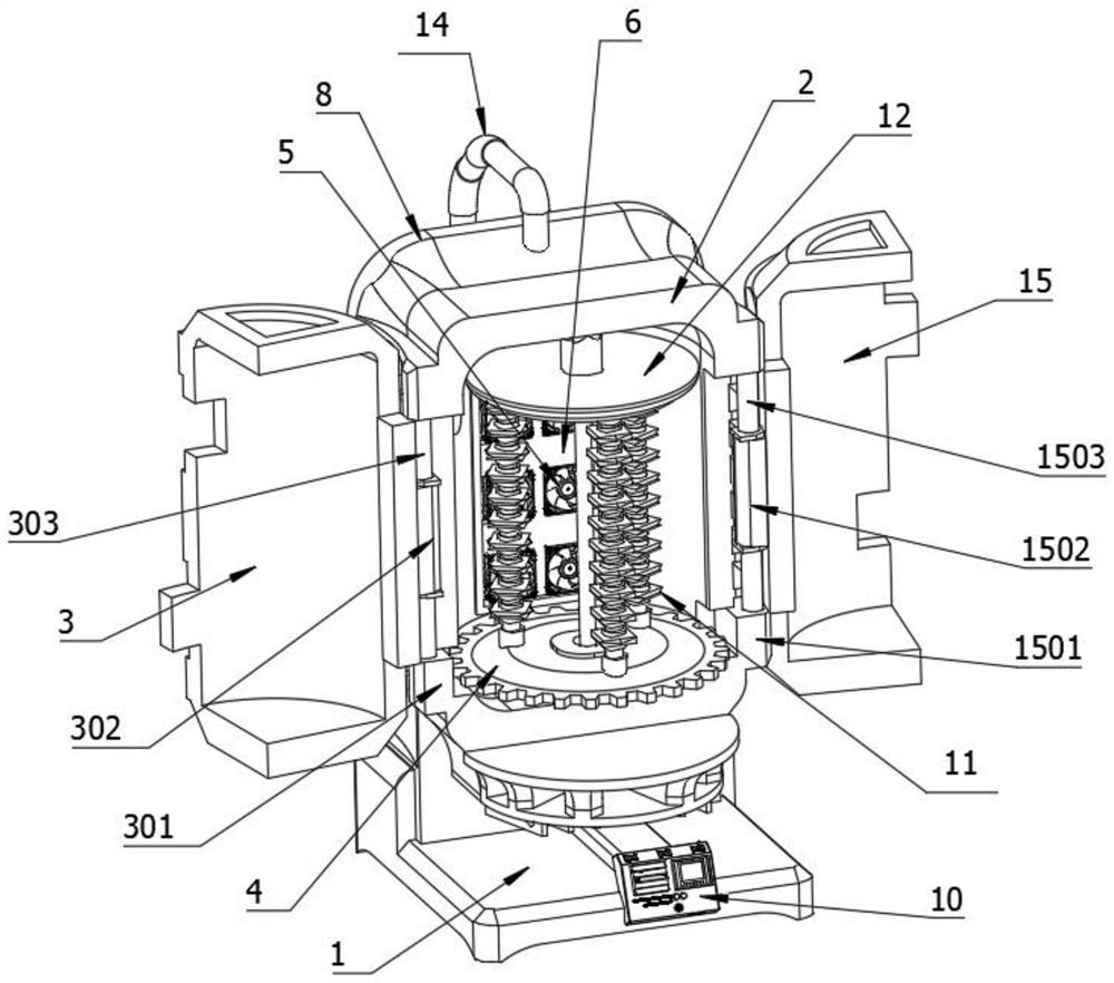
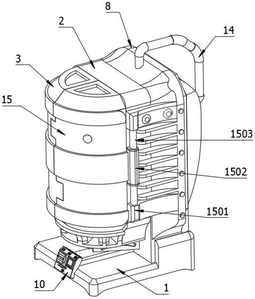
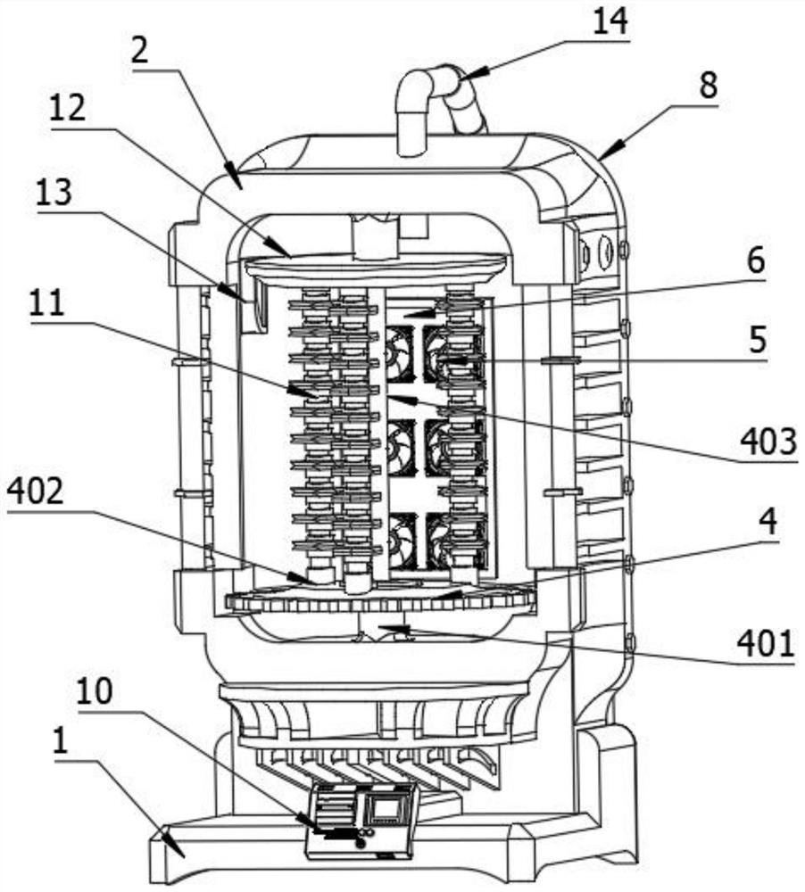
[0035] see Figure 1-8 , the present invention provides a technical solution: a vacuum coating device for high-voltage ion bombardment, including a base 1, the upper surface of the base 1 is fixedly connected with a main casing 2, and the two sides of the bottom of the front surface of the main casing 2 are respectively fixedly connected There are a first motor 301 and a second motor 1501, the output shafts of the first motor 301 and the second motor 1501 are respectively welded with the first connecting shaft 303 and the second connecting shaft 1503, the first connecting shaft 303 and the second connecting shaft 1503 The outer surface is welded with the first connecting rod 302 and the second connecting rod 1502 respectively, the outer surface of the first connecting rod 302 is welded with the right rotation housing 3, the outer surface of the second connecting rod 1502 is welded with the left rotation housing 15, the main The inner wall of the housing 2 is welded with a thir...


PUM


Abstract

The invention discloses a high-pressure ion bombardment vacuum coating device and a coating method thereof. The high-pressure ion bombardment vacuum coating device comprises a base, a main shell is fixedly connected to the upper surface of the base, a first connecting rod and a second connecting rod are welded to the outer surface of a first connecting shaft and the outer surface of a second connecting shaft respectively, a right rotating shell is welded to the outer surface of the first connecting rod, a left rotating shell is welded to the outer surface of the second connecting rod, a thirdmotor is welded to the inner side wall of the main shell, and an output shaft of the third motor is fixedly connected with a rotating base. All electrical components are conducted through programmingof a programmable logic controller, so that automatic control is realized. Chemical hot gas generated from coating material is decomposed into non-condensable gas and water which are harmless to humanhealth through fraction of an evaporator, then the non-condensable gas and the water are discharged, the water can be recycled after being refined from the outside, and the non-condensable gas is guided into the device through a gas guide pipe to provide heat and pressure as a useful waste.

Description

technical field [0001] The invention relates to the technical field of vacuum coating devices, in particular to a high-voltage ion bombardment vacuum coating device and a coating method thereof. Background technique [0002] As a branch of physical vapor deposition technology, high-voltage ion vacuum coater is a new coating preparation technology developed on the basis of vacuum evaporation and vacuum sputtering. It is an efficient, harmless and pollution-free ion coating equipment, which has the advantages of fast deposition speed, high ionization rate, large ion energy, simple equipment operation, low cost and large production capacity. Therefore, it has been widely used in the field of material surface modification. It can be applied not only to coating hard coatings, such as cutting tools, molds and wear-resistant and corrosion-resistant parts, but also to coating protective coatings, such as aircraft engine blades, automobile steel plates, heat sinks, etc. [0003] Wi...

Claims


Application Information

Patent Timeline
Patent Type & Authority Applications(China)
IPC IPC(8): C23C14/32C23C14/54
CPCC23C14/32C23C14/54
Inventor 张益明刘宇其他发明人请求不公开姓名
Owner 张益明
Learn More