Multifunctional lathe for automobile part manufacturing and machining
A kind of auto parts, multi-functional technology, applied in the direction of manufacturing tools, metal processing equipment, metal processing machinery parts, etc., can solve the problems of high use limitation, damage of auto parts, poor practicability, etc., to ensure stability, avoid damage, Good cooling and lubricating effect
- Summary
- Abstract
- Description
- Claims
- Application Information
AI Technical Summary
Problems solved by technology
Method used
Image
Examples
Embodiment 1
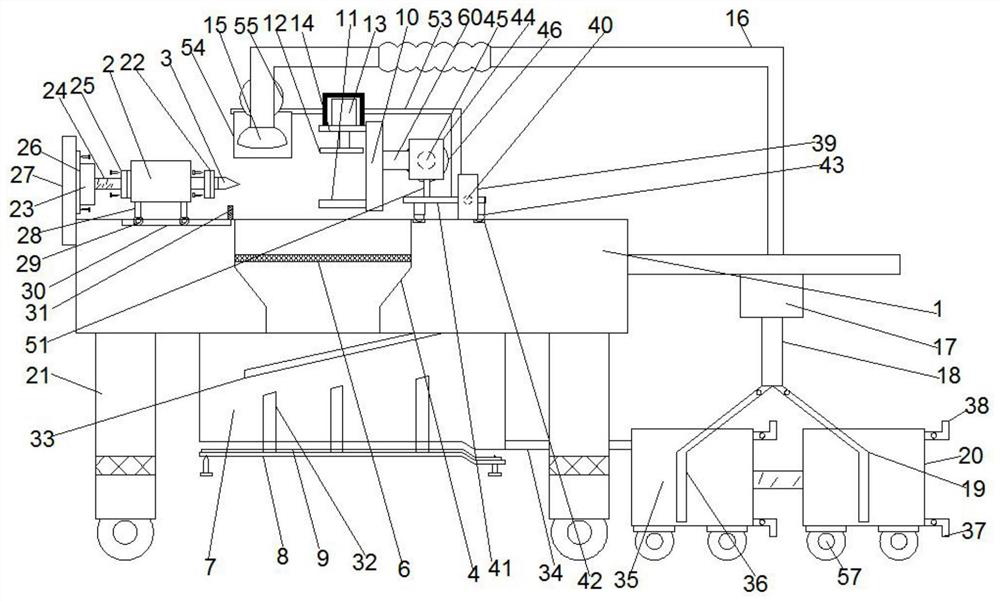
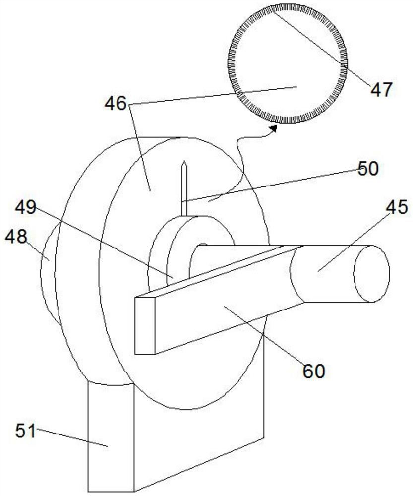
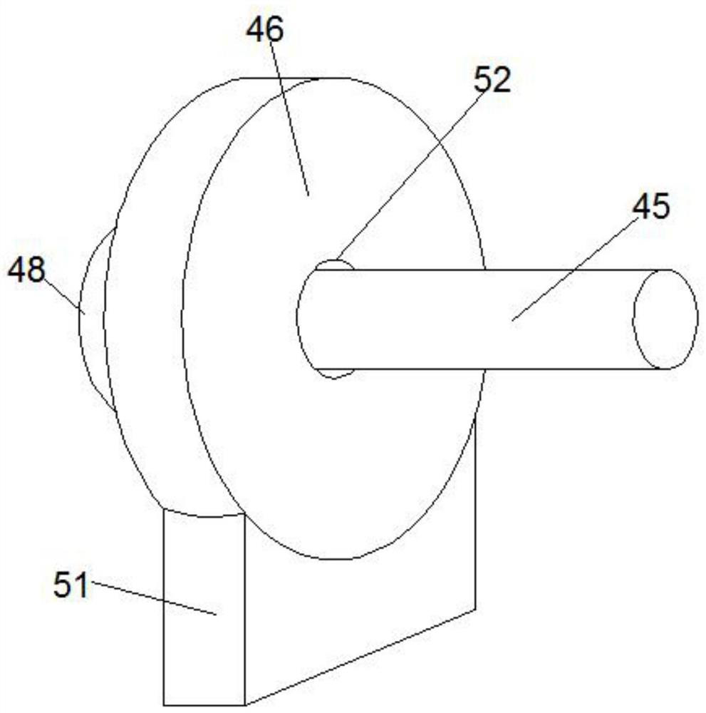
[0032] see Figure 1-7 According to an embodiment of the present invention, a multifunctional lathe for manufacturing and processing automobile parts, the workbench 1 is provided with a motor one 2 above the top of the workbench 1, and a drill bit 3 is connected to the output end of the motor one 2, The drill bit 3 is connected to a moving mechanism, and a vertical plate 10 is arranged above the top of the workbench 1, and the vertical plate 10 is fixedly provided with a splint 11 on one side of the drill bit 3, and one side of the vertical plate 10 is located on the The top of described splint 11 is provided with secondary splint 12, and described secondary splint 12 is fixed on the output bottom end of secondary telescopic motor 13, and described telescopic motor 13 is fixed on the support plate 14, and the output end of described secondary telescopic motor 13 wears Through the support plate 14, the support plate 14 is fixed on the vertical plate 10, the telescopic motor 13 ...
Embodiment 2
[0034] see figure 1 , for the drill bit 3, the drill bit 3 and the output end of the motor-2 are fixed on the fixed plate 22, the fixed plates 22 are fixed by screws, and the protective cover is fixed by screws on the support plate 14.
[0035] Through the above scheme of the present invention, the beneficial effect is that the fixing plate 22 is fixed on the drill bit 3 and the output end of the motor one 2, and is fixed by screws, so it is convenient to disassemble the drill bit 3 for replacement.
Embodiment 3
[0037] see figure 1 , for the moving mechanism, the moving mechanism is a telescopic motor one 23, the output end of the telescopic motor one 23 is connected to the mobile telescopic rod 24, and the mobile telescopic rod 24 and the motor one 2 are fixedly connected plate 25, the connecting plates 25 are fixed by screws, and the telescopic motor one 23 is fixed on the vertical plate 27 through the secondary connecting plate 26 with screws, and the vertical plate 27 is fixed on one side of the outer wall of the workbench 1 The bottom end of the motor one 2 is fixedly provided with two groups of roller rods 28, the roller rods 28 of each group are arranged horizontally, and the number of the roller rods 28 of each group is two. Roller bars 28 bottom ends are equipped with rollers 29, and the top surface of the workbench 1 is provided with two roller grooves 30 arranged transversely. In the roller groove 30 , a limit block 31 is fixed on the top of the workbench 1 , and the limit...
PUM
 Abstract
Description
Claims
Application Information
 - R&D
- Intellectual Property
- Life Sciences
- Materials
- Tech Scout
- Unparalleled Data Quality
- Higher Quality Content
- 60% Fewer Hallucinations
Browse by: Latest US Patents, China's latest patents, Technical Efficacy Thesaurus, Application Domain, Technology Topic, Popular Technical Reports.
© 2025 PatSnap. All rights reserved.Legal|Privacy policy|Modern Slavery Act Transparency Statement|Sitemap|About US| Contact US: help@patsnap.com


