Innovative welding tool clamping device

A clamping device and welding tooling technology, applied in auxiliary devices, welding equipment, auxiliary welding equipment, etc., can solve the problems of high parts production cost, high product repair cost, high scrap rate, and improve product qualification rate and production efficiency. , The effect of reducing the number of maintenance and repairs, and reducing the workload of rework

Pending Publication Date: 2020-12-25
ZHEJIANG WANXIANG SYST +1
View PDF0 Cites 0 Cited by
  • Summary
  • Abstract
  • Description
  • Claims
  • Application Information

AI Technical Summary

Problems solved by technology

The second type is formed by aluminum alloy extrusion casting process, which is mostly used for B-class and above models, and is used for weight reduction and light weight of the body, with stable dimensions and good mechanical properties. Due to the domestic aluminum alloy sub-frame is subject to structural design, development capabilities and The level of aluminum alloy production technology is limited. At the same time, domestic self-developed brand models are mainly aimed at the low-end market and cannot bear the high production cost of parts. Therefore, domestic self-owned brand models have less casting technology and are mostly used for welding and forming.
The existing technical solutions mainly have the following defects: the development of the fixture clamping device is difficult, there are many types of spare parts, the structure is complex, easy to damage, and the maintenance cost is high
When the support seat 306 and the original positioning pin 302 are loose, it is easy to cause product inclination and poor batch of beams, resulting in high scrap rate and high product repair cost

Method used


Image

  • Innovative welding tool clamping device
  • Innovative welding tool clamping device
  • Innovative welding tool clamping device

Examples


Embodiment

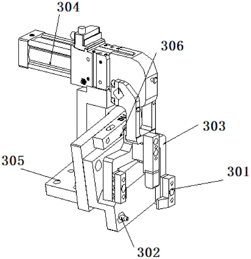
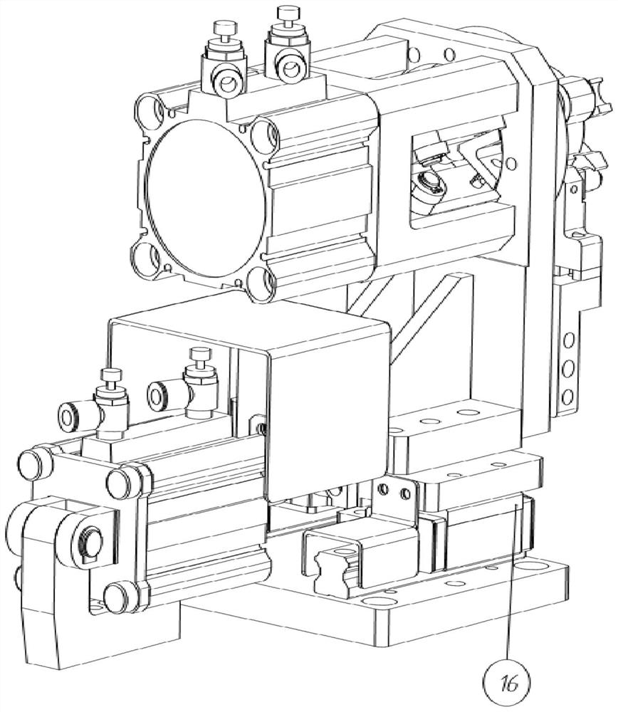
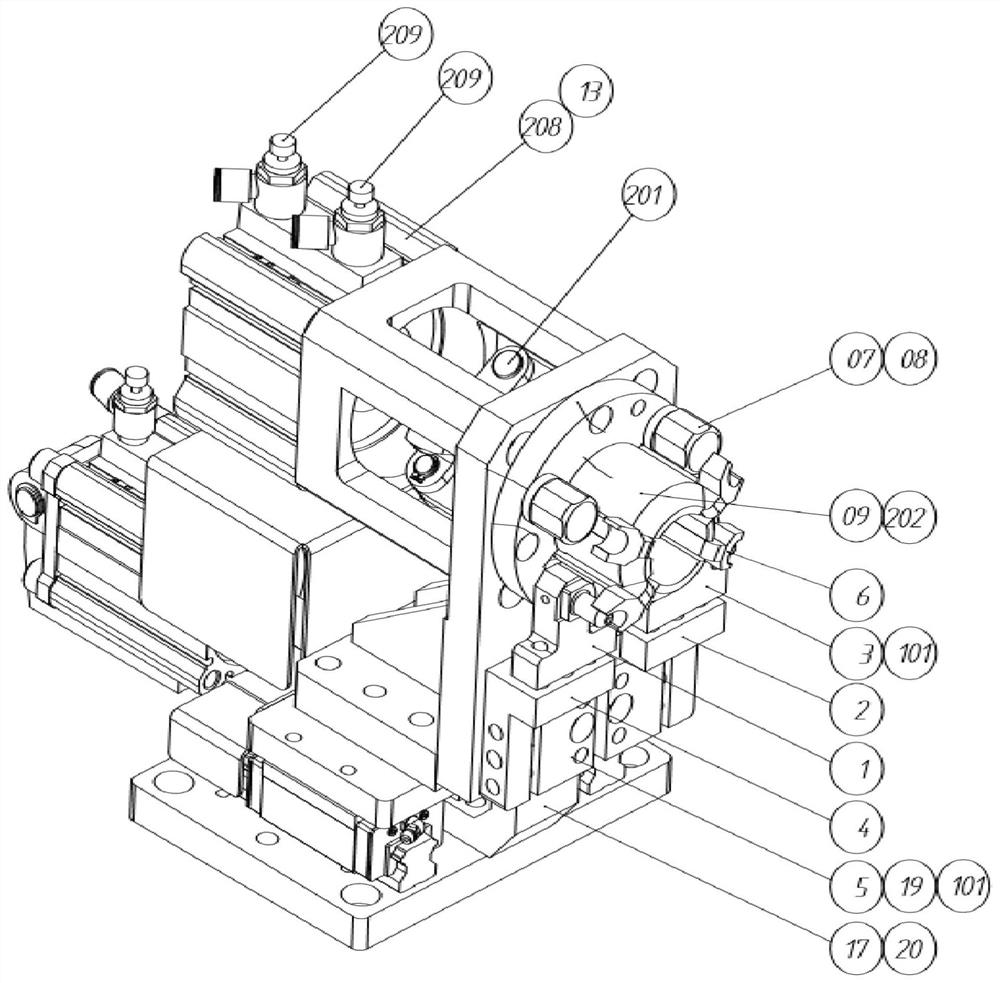
[0018] Embodiment: As shown in the accompanying drawings, this innovative welding tool clamping device mainly includes connecting block A1, connecting block B2, connecting block C3, connecting block D4, connecting block E5, pressing block 6, supporting block 7, and adjusting pads Sheet A8, connecting block F9, corner seat 10, connecting block G11, connecting block H12, connecting block I13, connecting block J14, connecting block K15, connecting block L17, connecting block M18, adjusting gasket B19, adjusting gasket C20, positioning Pin 24, adjusting gasket D101, hinge pin A201, hinge pin B202, cylinder A203, guide rail 207, cylinder B208, connect block M18 on the middle part of connection block K15, install guide rail 207 on both sides of connection block K15, and install on connection block M18 The cylinder A203 is provided with a regulating valve A204, and a protective cover B23 is installed outside the cylinder A203. The cylinder A203 is connected to the corner seat 10, and...


PUM


Abstract

The invention discloses an innovative welding tool clamping device. The device mainly comprises pressing blocks and the like, wherein a connecting block M is installed in the upper middle of a connecting block K, guide rails are installed on the two sides of the connecting block K, an air cylinder A is installed on the connecting block M, the air cylinder A is connected with an angle seat, the angle seat is installed on the guide rails, an air cylinder B is installed on the angle seat, the front end of the air cylinder B is connected with the pressing blocks which are arranged in the circumference by means of hinge pins A and connecting blocks H, supporting blocks and adjusting gaskets A are arranged on the outer sides of the pressing blocks, connecting blocks F and hinge pins B are arranged among the pressing blocks, and positioning pins are arranged beside the pressing blocks. According to the innovative welding tool clamping device, a clamping device for a rear torsion beam brake support is innovated, rapid clamping is achieved, and parts are convenient to take; the accuracy of the caster angle and the toe-in angle of the rear torsion beam brake mounting surface after welding isimproved, the rejection rate of products and the repair workload of unqualified parts are reduced, the product size is stable, and the product percent of pass and the production efficiency are improved; and the effect of being easy to operate is achieved, the service life of a clamp is prolonged, and the cost is reduced.

Description

technical field [0001] The invention relates to the field of automobile manufacturing, in particular to an innovative welding tool clamping device. Background technique [0002] Among domestic self-developed models, the quality requirements for the rear torsion beam of the body chassis are strict, and the four-wheel alignment accuracy of the vehicle is high, the production is difficult, the number of accessories is large, and the structure is complex. The above focus will be on the accuracy, stability and speed of the welding tooling. . At present, there are two methods for the production of body chassis parts: the first method is to fix the steel stamping parts on the welding tool, and use the welding equipment and the mixed gas (Ar+O2+CO2) to weld the shape. The specific operation method is: first, use the welding tool The stamping parts are fixed at the first reference point, and then all steel workpieces are clamped, the switch is started, clamped, and the equipment is ...

Claims


Application Information

Patent Timeline
Patent Type & Authority Applications(China)
IPC IPC(8): B23K37/04
CPCB23K37/0435
Inventor 徐圆戴凯宁
Owner ZHEJIANG WANXIANG SYST
Why Eureka
Try Eureka