
Hydraulic actuator for robot

A hydraulic actuation and robot technology, applied in fluid pressure actuation devices, fluid pressure actuation system testing, mechanical equipment, etc., can solve the problem of inability to achieve impact buffering, impact energy absorption, and controllable release of impact energy stored problems, to achieve the effect of increasing anti-interference ability, reducing energy consumption, and high load capacity

Active Publication Date: 2020-12-22
HARBIN INST OF TECH
View PDF11 Cites 0 Cited by
  • Summary
  • Abstract
  • Description
  • Claims
  • Application Information

AI Technical Summary

Problems solved by technology

[0004] Based on the above deficiencies, the purpose of the present invention is to provide a hydraulic actuator for robots to solve the problems that the current swing joint drive cannot realize impact buffering, impact energy absorption and storage, impact energy controllable release, and force burst. and achieve higher power density

Method used


Image

  • Hydraulic actuator for robot
  • Hydraulic actuator for robot
  • Hydraulic actuator for robot

Examples


Embodiment 1

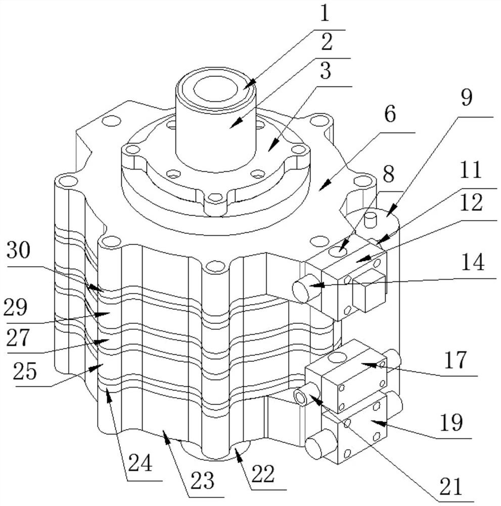
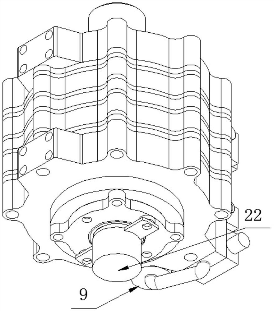
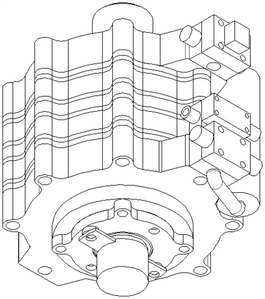
[0038]Such asFigure 1-14 As shown, a hydraulic actuator mechanism for a robot includes a vane-type swing hydraulic motor, a rotary encoder, a servo valve, a high-speed three-position four-way electromagnetic directional valve, a pressure reducing valve, a one-way valve, an accumulator, and two A pressure sensor, a rotary encoder is installed at the tail of a vane-type swing hydraulic motor. The vane swing hydraulic motor is cylindrical and includes an output shaft, a head carbon fiber end cover 6, a tail carbon fiber end cover 23, and two bearing end covers 5. Two sets of needle bearings 46, head aluminum alloy gland 30, tail aluminum alloy gland 24, main aluminum alloy cylinder 29, auxiliary aluminum alloy cylinder 25, middle partition 27, outer end of head aluminum alloy gland 30 Connected with the first bearing end cover, the head aluminum alloy gland 30 is equipped with the first needle roller bearing, the head aluminum alloy gland 30 is connected to the outer carbon fiber end c...


PUM


Abstract

The invention discloses a hydraulic actuator for a robot. The hydraulic actuator comprises a blade type swing hydraulic motor, a rotary encoder, a servo valve, a high-speed three-position four-way electromagnetic reversing valve, a pressure reducing valve, a one-way valve, an energy accumulator and two pressure sensors, wherein the blade type swing hydraulic motor comprises an output shaft and twoindependently sealed cylinder bodies, the upper half portion of the interior of each cylinder body in the radial direction is a containing cavity, the lower half portion of the interior of each cylinder body is a stator integrated with the cylinder body, the output shaft is rotationally connected with grooves in the surfaces of the stators in the axial centers of the two cylinder bodies, a bladeis arranged in each cylinder body, the end faces of the blades make contact with the inner walls of the cylinder bodies in an attached mode, the radial surfaces of the blades can make contact with thesurfaces of the stators, and the output shaft is fixedly connected with the two blades. According to the hydraulic actuator, the energy consumption is greatly reduced, the instantaneous output is increased, and a swing joint can instantaneously obtain a higher movement speed.

Description

Technical field[0001]The invention specifically relates to a hydraulic actuator for a robot.Background technique[0002]The swing joint is derived from bionics, which provides connection support for the rods with relative motion and drives the two connected rods to move relative to each other, which is similar to the movement of human arms, legs and feet. Swing joints are widely used in the field of robotics, such as robotic arms on assembly lines, various legged walking robots (biped robots, quadruped robots, etc.). Swing joints are the most basic drive unit of the above-mentioned robots, and their performance is direct. It determines the motion performance of the motion system, as the robot develops toward higher speed motion, greater load bearing, higher motion accuracy, higher anti-interference, and higher endurance. The basic requirement of higher speed movement and greater load bearing on the swing joint is high power density, that is, a higher power output can be achieved under...

Claims


Application Information

Patent Timeline
Patent Type & Authority Applications(China)
IPC IPC(8): F15B11/00F15B13/02F15B1/04F15B15/12F15B19/00
CPCF15B11/00F15B13/02F15B13/027F15B13/025F15B1/04F15B15/12F15B19/005F15B2211/71
Inventor 丛大成李加启杨志东杨宇江磊
Owner HARBIN INST OF TECH
Learn More