Micro-channel heat exchanger and heat pump system

A micro-channel heat exchanger and header technology, applied in the field of heat pump systems, can solve problems such as uneven distribution of refrigerant, achieve the effect of improving uneven distribution of refrigerant, uniform distribution, and improving heat exchange performance

Pending Publication Date: 2020-12-15
GREE ELECTRIC APPLIANCES INC
View PDF0 Cites 1 Cited by
  • Summary
  • Abstract
  • Description
  • Claims
  • Application Information

AI Technical Summary

Problems solved by technology

[0005] One of the objectives of the present invention is to propose a microchannel heat exchanger and heat pump system, which solves the technical problem of uneven distribution of refrigerant entering the flat tube when the microchannel heat exchanger is used as an evaporator in the prior art

Method used


Image

  • Micro-channel heat exchanger and heat pump system
  • Micro-channel heat exchanger and heat pump system
  • Micro-channel heat exchanger and heat pump system

Examples


Embodiment 1

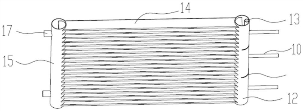
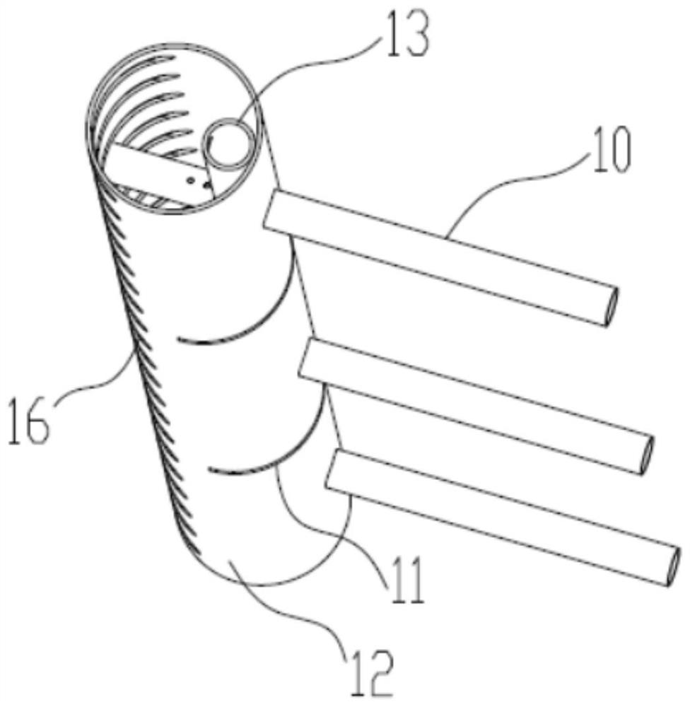
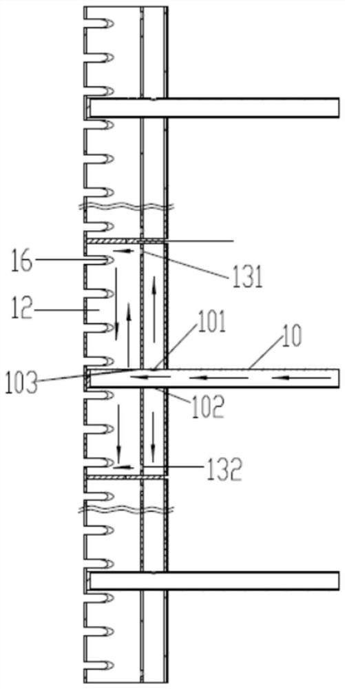
[0034] This embodiment is attached in conjunction with the instructions Figure 1-6 The microchannel heat exchanger of the present invention will be described in detail.

[0035] The microchannel heat exchanger 1 of the present embodiment includes double headers and perforated inner inserts 10, such as Figure 1~5 shown. Preferably, the perforated inner tube 10 passes through the double header and is in contact with the inner wall of the double header, and the perforated inner tube 10 is at least provided with an upper hole 101 of the inner tube and a lower hole of the inner tube. hole 102 and the injection hole 103 of the inner insertion tube, and make the refrigerant in the opening inner insertion tube 10 enter the double header through the upper hole 101 of the inner insertion tube and the injection hole 103 of the inner insertion tube and then connect with the lower hole of the inner insertion tube 102 The refrigerant mixed in the double header, such as image 3 Or 4 or...

Embodiment 2

[0050] This embodiment is attached in conjunction with the instructions Figure 7 The heat pump system of the present invention will be described in detail.

[0051] The heat pump system of this embodiment includes the microchannel heat exchanger 1 of any technical solution in Embodiment 1, and the heat pump system of this embodiment also includes a four-way valve 2, a compressor 3, a heat exchanger 4, and a throttling device 5 and shunt 6, such as Figure 7 shown. The heat pump system of this embodiment has the microchannel heat exchanger 1 of any one of the technical solutions in Embodiment 1, so that the heat exchange performance of the heat pump system can be improved.

[0052] When the micro-channel heat exchanger 1 is used as a condenser, the pipe a of the four-way valve 2 is connected to the pipe b, and the pipe c is connected to the pipe d. The refrigerant discharged from the compressor 3 enters the micro-channel heat exchanger after passing through the four-way valv...


PUM


Abstract

The invention discloses a micro-channel heat exchanger and a heat pump system, relates to the technical field of heat pump systems, and solves the technical problem in the prior art that refrigerantsentering a flat pipe are non-uniformly distributed when the micro-channel heat exchanger is used as an evaporator. The micro-channel heat exchanger comprises a double collecting pipe and opening innerinserting pipes, wherein the opening inner inserting pipes penetrate through the double collecting pipe and are in contact with the inner wall surface of the double collecting pipe; an inner inserting pipe upper hole, an inner inserting pipe lower hole and an inner inserting pipe spray hole are at least formed in each opening inner inserting pipe; and the refrigerants in the opening inner inserting pipes separately enter the double collecting pipe through the corresponding inner inserting pipe upper holes and inner inserting pipe spray holes and then are mixed with the refrigerants entering the double collecting pipe through the corresponding inner inserting pipe lower holes. According to the micro-channel heat exchanger and the heat pump system, the refrigerants are uniformly distributedin a cavity of the double collecting pipe, so that the refrigerants can be uniformly distributed in the flat pipe, and the heat exchange performance of the micro-channel heat exchanger can be improved.

Description

technical field [0001] The invention relates to the technical field of heat pump systems, in particular to a microchannel heat exchanger and a heat pump system comprising the microchannel heat exchanger. Background technique [0002] When the microchannel heat exchanger is used as an evaporator, the imported refrigerant is generally in a gas-liquid two-phase state, while the header of the traditional microchannel heat exchanger has no diversion measures, and the gas-liquid two-phase refrigerant stratification phenomenon is obvious after entering the header , resulting in uneven distribution of refrigerant entering the flat tube, resulting in poor heat transfer performance of the heat exchanger. [0003] Patent JPA2019074287 provides a microchannel heat exchanger double header, the inner tube and the outer tube are on the same axis, the gas-liquid two-phase refrigerant enters the header from the bottom of the inner tube, and passes through the double header. Holes or slits i...

Claims


Application Information

Patent Timeline
Patent Type & Authority Applications(China)
IPC IPC(8): F28D1/053F25B30/02F25B39/04
CPCF25B30/02F25B39/04F28D1/05325
Inventor 王凯吴迎文杨瑞琦
Owner GREE ELECTRIC APPLIANCES INC
Why Eureka
Try Eureka