Eureka AIR delivers breakthrough ideas for toughest innovation challenges, trusted by R&D personnel around the world.

Reinforcing and lifting method for strip-shaped or box-shaped foundation building

A box-shaped foundation and strip-shaped foundation technology, which is used in construction, infrastructure engineering, soil protection and other directions to ensure stability, reduce damage, and ensure stability.

Active Publication Date: 2020-12-15
BEIJING HENGXIANG HONGYE FOUND REINFORCEMENT TECH CO LTD
View PDF3 Cites 2 Cited by
  • Summary
  • Abstract
  • Description
  • Claims
  • Application Information

AI Technical Summary

Problems solved by technology

[0003] The object of the present invention is to provide a method for strengthening and lifting a bar-shaped or box-shaped foundation building, which solves the problem of settlement, lifting and reinforcement of a strip-shaped or box-shaped foundation building, and has good overall stability, little damage to the building and Advantages of preventing re-sedimentation

Method used


Image

  • Reinforcing and lifting method for strip-shaped or box-shaped foundation building
  • Reinforcing and lifting method for strip-shaped or box-shaped foundation building
  • Reinforcing and lifting method for strip-shaped or box-shaped foundation building

Examples


Embodiment 1

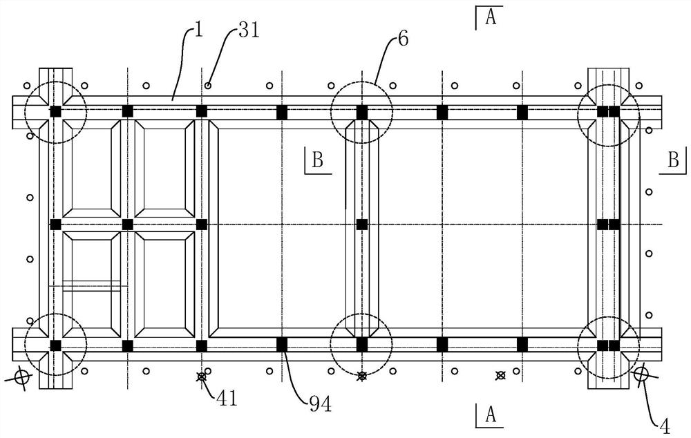
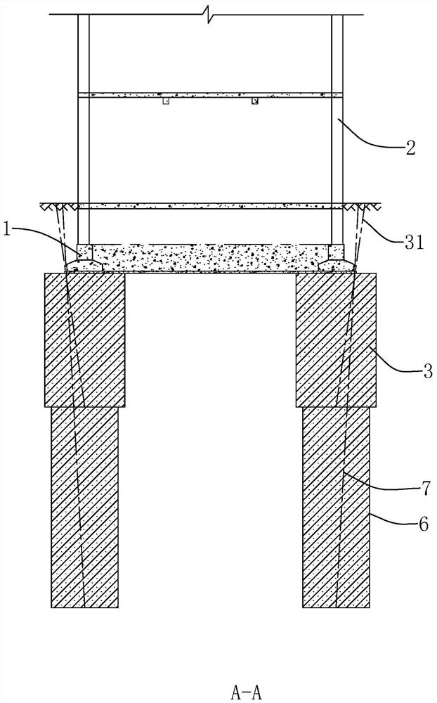
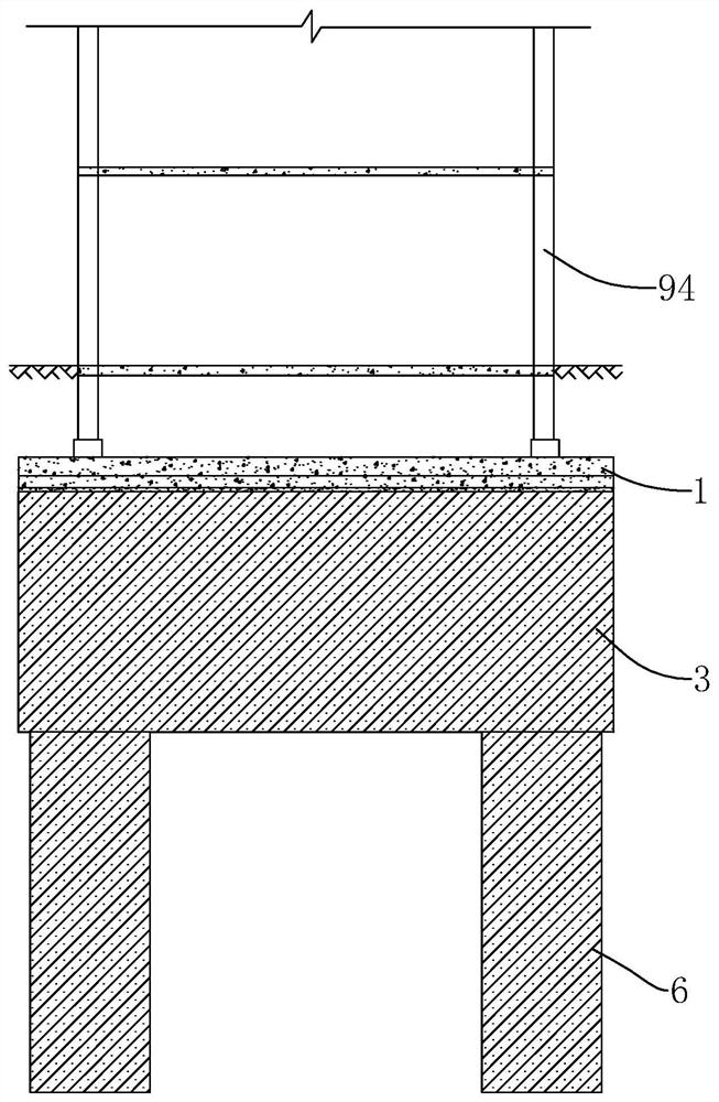
[0063] The invention discloses a method for strengthening and lifting a strip-shaped or box-shaped foundation building. This embodiment takes a strip-shaped foundation 1 building as an example for illustration. Such as figure 1 As shown, a building with a strip foundation 1 includes intersecting strip foundations 1 , and structural columns 94 are arranged at intervals on the strip foundation 1 , and walls are arranged between the structural columns 94 . The reinforcement lifting method includes the following steps:

[0064] S1. Layout of measuring points: a plurality of measuring points are evenly arranged around the outer contour of the building, which can be arranged on the strip foundation 1, preferably at the position of the structural column 94; use a level to measure the elevation of each measuring point, according to the measured The elevation of the points determines that the side of the four corners of the building where the two points with the largest settlement are...

Embodiment 2

[0088] When the foundation of the building is a special stratum such as collapsible loess and miscellaneous fill, the drilling and grouting operations shall adopt the integral forward grouting process instead of the integral backward grouting. Because the overall retreat grouting construction needs to drill the drill pipe to the design depth at one time, during the process of drilling to the design depth, the water sprayed from the drill bit will soften the surrounding soil, resulting in secondary settlement of the building. When drilling in collapsible loess, although the drilling speed is fast and there is not much water out of the drill bit, the plan of drilling to the design depth at one time cannot be adopted because the collapsible loess will subside when it meets water. When drilling in miscellaneous fill soil layers, backfilled flakes are often encountered. When drilling into flakes, the drilling speed slows down and more water is released from the drill bit, which will...

Embodiment 3

[0102] This embodiment mainly introduces the reinforcement and lifting of the box-shaped foundation building. The difference from Embodiments 1 and 2 is that all the above strip foundations 1 are equivalent to the partition wall 10 in the box foundation, and the above-mentioned outer wall is equivalent to the partition wall 10 located on the outermost periphery in the box foundation, and the reinforcement injection The grout hole 31, the lifting hole 4 and the pile foundation hole 7 all need to penetrate the bottom plate 101 of the box foundation.

[0103] When raising buildings with box foundations, it is preferred, as in Figure 17 As shown in , each corner of the building on the lifting side is correspondingly arranged with two lifting holes 4, and the two lifting holes 4 are respectively located on the outside of the two mutually perpendicular outer contour lines of the strip foundation 1; Directly below exterior wall 2.

[0104] After the lifting step of S4, and between...


PUM

PropertyMeasurementUnit
Diameteraaaaaaaaaa

Abstract

The invention relates to a reinforcing and lifting method for a strip-shaped or box-shaped foundation building. The reinforcing and lifting method comprises the following steps that the lifting side of the building is determined according to the elevations of measuring points; a plurality of reinforcing grouting holes inclining downwards are formed in the side surface of a strip-shaped foundationor a box-shaped foundation partition wall at intervals, and a reinforcing body is formed below the strip-shaped foundation or the partition wall by adopting pressure grouting in the reinforcing grouting holes; lifting holes inclining downwards are formed in the two ends close to the lifting side of the building; and the lifting holes go deep into the bottom of the reinforcing body, pressure grouting is carried out in the lifting holes at the same time, the reinforcing body is used as a buffer strip, the lifting side of the building is lifted, the lifting speed is controlled, the elevations oftwo corners are finally lifted to the same elevations as the elevations of corners corresponding to the non-lifting side of the building at the same time, then a reinforcing pile foundation is formedbelow the reinforcing body, and the reinforcing pile foundation and the reinforcing body jointly support the strip-shaped foundation. The reinforcing and lifting method has the advantages of being good in overall stability, controllable in lifting speed and height, small in damage to the building and capable of preventing secondary sedimentation.

Description

technical field [0001] The invention relates to the technical field of building foundation uplift and reinforcement, in particular to a method for reinforcement and uplift of a bar-shaped or box-shaped foundation building. Background technique [0002] Due to reasons such as architectural survey, design, construction or bad weather, the completed building will sink due to insufficient foundation strength. If the inclination value of the building exceeds the allowable inclination value, it will affect the normal use, even crack and damage, posing a threat to the structural safety of the building. At this time, it is necessary to carry out lifting correction and foundation reinforcement. The existing lifting correction method generally adopts polyurethane grouting for lifting. The polyurethane grouting method is to inject polyurethane foam reaction raw materials into the foundation, and to fill, infiltrate, compact, replace and reinforce the reinforced soil through the huge e...

Claims


Application Information

Patent Timeline
IPC IPC(8): E02D35/00E02D3/12
CPCE02D35/005E02D3/12
Inventor 崔学栋吴继光崔腾跃
Owner BEIJING HENGXIANG HONGYE FOUND REINFORCEMENT TECH CO LTD
Why Eureka
Eureka Blog
Learn More