
Rust removing and chamfering equipment provided with multi-edge processing structure and used for machining electronic parts

A technology for spare parts and electronics, which is applied in the field of rust removal and chamfering equipment, can solve the problems of insufficient functionality, inability to chamfer electronic parts at the same time, and lack of a multilateral processing structure, so as to strengthen the fixed structure and increase the dust collection range. , the effect of improving processing efficiency

Pending Publication Date: 2020-12-15
深圳市华博自动化设计有限公司
View PDF0 Cites 1 Cited by
  • Summary
  • Abstract
  • Description
  • Claims
  • Application Information

AI Technical Summary

Problems solved by technology

[0004] The purpose of the present invention is to provide a kind of derusting and chamfering equipment with multilateral processing structure for processing electronic parts, to solve the problem that the existing derusting and chamfering equipment for processing electronic parts does not have a multilateral processing structure. , it is not possible to chamfer multiple positions of electronic parts at the same time, and it is not convenient to position and fix electronic parts during the chamfering process, and it is not possible to derust and polish the surface of electronic parts at the same time. Insufficient problem

Method used


Image

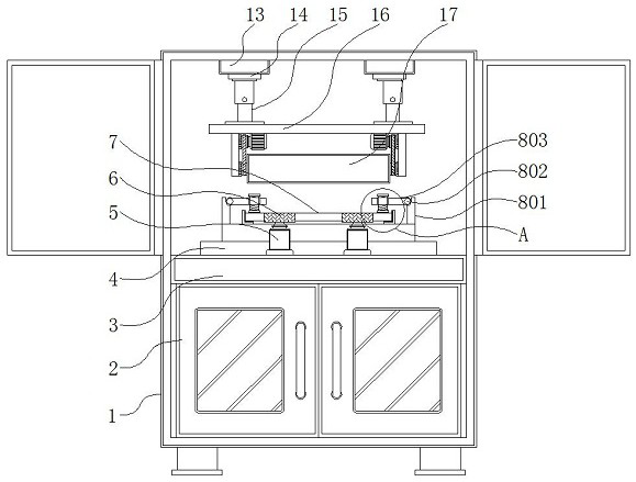
  • Rust removing and chamfering equipment provided with multi-edge processing structure and used for machining electronic parts
  • Rust removing and chamfering equipment provided with multi-edge processing structure and used for machining electronic parts
  • Rust removing and chamfering equipment provided with multi-edge processing structure and used for machining electronic parts

Examples


Embodiment Construction

[0028] The technical solutions in the embodiments of the present invention will be clearly and completely described below in conjunction with the accompanying drawings in the embodiments of the present invention. Obviously, the described embodiments are only some of the embodiments of the present invention, not all of them. Based on The embodiments of the present invention and all other embodiments obtained by persons of ordinary skill in the art without making creative efforts belong to the protection scope of the present invention.

[0029] In the description of the present invention, unless otherwise stated, the meaning of "plurality" is two or more; the terms "upper", "lower", "left", "right", "inner", "outer" , "front end", "rear end", "head", "tail", etc. indicate the orientation or positional relationship based on the orientation or positional relationship shown in the drawings, and are only for the convenience of describing the present invention and simplifying the desc...


PUM


Abstract

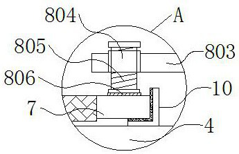
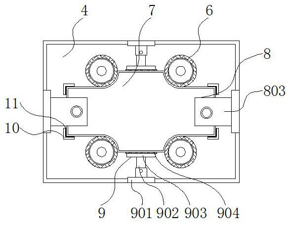
The invention discloses rust removing and chamfering equipment provided with a multi-edge processing structure and used for machining electronic parts, and relates to the technical field of machiningof the electronic parts. The equipment comprises a machine body, a dust suction mechanism and a polishing and rust removal mechanism; a storage cabinet is arranged on the lower side inside the machinebody; a supporting seat is fixed to the upper side of the storage cabinet; a machining platform is fixed to the middle of the upper side of the supporting seat; rotating motors are embedded in the two sides inside the machining platform; chamfering discs are mounted above the rotating motors; a main electronic part body is arranged between the chamfering discs and is located above the middle of the machining platform; first positioning mechanisms are arranged on the left side and the right side of the upper side of the machining platform; and second positioning mechanisms are arranged on thefront side and the back side of the upper side of the machining platform. The equipment has the beneficial effects that the chamfering discs are conveniently driven to rotate through the rotating motors, so that the chamfering discs can be used for polishing and deburring chamfers of the main electronic part body.

Description

technical field [0001] The invention relates to the technical field of electronic spare parts processing, in particular to a rust removal and chamfering equipment with a multilateral processing structure for electronic spare parts processing. Background technique [0002] Electronic parts and accessories are part of electronic parts and are the basis of electronic products. Electronic parts and components are components of small machines and instruments. They are often composed of several parts and can be used in similar products. Since the late 1990s, all kinds of electronic products that integrate the three major fields of computer, information and communication, and consumer electronics have begun to penetrate into family life extensively. The end is chamfered. In the process of electronic component processing, chamfering equipment is needed to chamfer it. [0003] The existing derusting and chamfering equipment for electronic parts processing does not have a multilatera...

Claims


Application Information

Patent Timeline
Patent Type & Authority Applications(China)
IPC IPC(8): B24B9/02B24B27/033B24B41/02B24B41/04B24B41/06B24B47/12B24B47/22B24B55/06B24B55/12
CPCB24B9/02B24B27/033B24B41/02B24B41/04B24B41/06B24B47/12B24B47/22B24B55/06B24B55/12
Inventor 黄军梅邝润森黄镇鹏
Owner 深圳市华博自动化设计有限公司
Learn More