
MPO multifilament drawing auxiliary device with ultrahigh squareness

An auxiliary device and squareness technology, which is applied in the field of microporous optical components MPO, can solve the problems of low yield rate, difficulty in meeting the technical requirements of multifilaments, and difficulty in controlling the squareness of MPO multifilaments, and achieve the effect of improving squareness

Active Publication Date: 2020-12-11
NORTH NIGHT VISION TECH
View PDF9 Cites 2 Cited by
  • Summary
  • Abstract
  • Description
  • Claims
  • Application Information

AI Technical Summary

Problems solved by technology

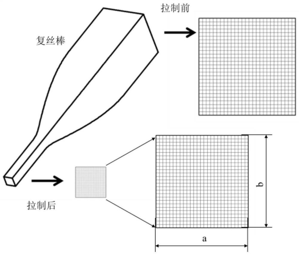
combine figure 2 The drawing process of the MPO multifilament rod shown, that is, the diameter change process, is currently extremely difficult to control the squareness of the MPO multifilament. In a high temperature environment, it is difficult for the drawn multifilament to meet the technical requirements, and the yield rate is low. How to ensure that the drawn multifilament rods have a relatively stable appearance and at the same time ensure that the multifilament rods are not damaged is the current difficulty in drawing ultra-high squareness MPO

Method used


Image

  • MPO multifilament drawing auxiliary device with ultrahigh squareness
  • MPO multifilament drawing auxiliary device with ultrahigh squareness
  • MPO multifilament drawing auxiliary device with ultrahigh squareness

Examples


Embodiment Construction

[0041] In order to better understand the technical content of the present invention, specific embodiments are given together with the attached drawings for description as follows.

[0042] Aspects of the invention are described in this disclosure with reference to the accompanying drawings, which show a number of illustrated embodiments. Embodiments of the present disclosure are not necessarily intended to include all aspects of the invention. It should be appreciated that the various concepts and embodiments described above, as well as those described in more detail below, can be implemented in any of numerous ways, since the concepts and embodiments disclosed herein are not limited to any implementation. In addition, some aspects of the present disclosure may be used alone or in any suitable combination with other aspects of the present disclosure.

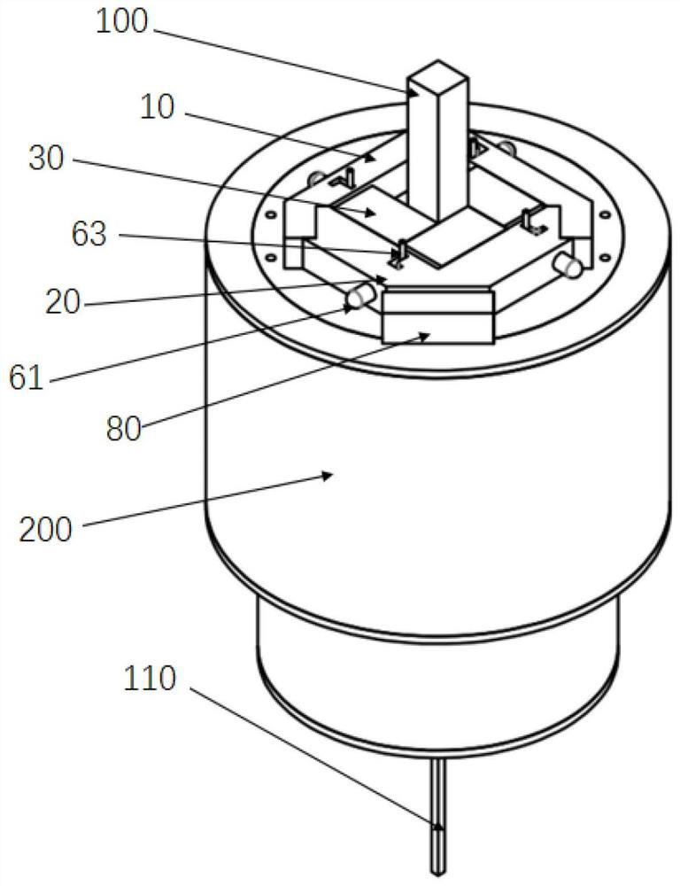
[0043] combine Figure 3-Figure 8 The ultra-high squareness MPO multi-filament drawing auxiliary device of the exemplary embo...


PUM


Abstract

The invention provides an MPO multifilament drawing auxiliary device with ultrahigh squareness. The device is arranged on the end surface of a drawing furnace and comprises: an outer clamp; an inner clamp, wherein the size of the inner clamp is smaller than that of the outer clamp, and the outer clamp and the inner clamp are installed diagonally, so that the outer clamp at least partially clamps the inner clamp, and a square enclosure is formed between the outer clamp and the inner clamp; a plurality of sliding blocks arranged in the square enclosure, wherein every two of the sliding blocks are adjacent to form a square hole located in the center; and through L-shaped grooves arranged on each edge of the outer clamp and the inner clamp and pushing mechanisms arranged in the L-shaped grooves, wherein the pushing mechanism can be switched between a locking state and a releasing state in the L-shaped groove, in the releasing state, a pushing rod is acted by a clamping spring and located in one side of a sliding groove in the direction perpendicular to the side face of the sliding block, contacts with the corresponding sliding block and is pressed, and in the locking state, the pushingrod is operated to overcome the elastic force of the clamping spring, and the pushing rod and the sliding block are clamped on the other side of the L-shaped groove, so that the overall squareness isguaranteed.

Description

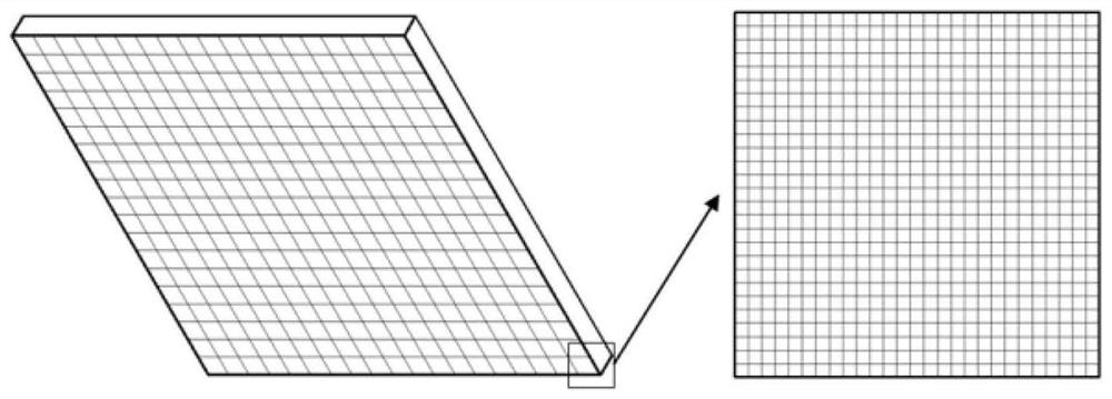
technical field [0001] The invention relates to the field of microporous optical element MPO technology, in particular to an ultra-high squareness MPO multifilament drawing auxiliary device. Background technique [0002] Micropore optics (MPO) is a grazing incidence high-energy ray focusing optical element, which can focus photons in x-ray and ultraviolet bands. like figure 1 The microstructure diagram of MPO is shown. MPO is a thin sheet of glass material with a porous structure consisting of millions of square micropores with a micron-scale size. The inner wall surface of the micropores has extremely low roughness. The shape of MPO can be divided into two types: plane and spherical. Among them, the plane MPO can converge the divergent light, and the spherical MPO can converge the parallel light. Among all currently known X-ray optical components, MPO has the smallest volume and mass while ensuring a large field of view and high resolution. [0003] The multifilament dra...

Claims


Application Information

Patent Timeline
Patent Type & Authority Applications(China)
IPC IPC(8): C03B37/025C03B37/03
CPCC03B37/0253C03B37/03Y02P40/57
Inventor 廖亦戴姜博文徐昭金戈张振李冬黎龙辉孙赛林周新张珈玮
Owner NORTH NIGHT VISION TECH
Learn More