Eureka AIR delivers breakthrough ideas for toughest innovation challenges, trusted by R&D personnel around the world.

Laser cladding deformation control method for slender piston rod

A laser cladding and deformation control technology, applied in metal material coating process, coating and other directions, can solve the problem of partial cladding part being too thick, piston rod deformation, iron leakage, etc. The effect of less powder and small spot

Inactive Publication Date: 2020-12-11
ZHENGZHOU COAL MINING MACHINERY GRP
View PDF6 Cites 3 Cited by
  • Summary
  • Abstract
  • Description
  • Claims
  • Application Information

AI Technical Summary

Problems solved by technology

[0003] The workpiece adopts the traditional laser cladding process as follows: blanking - rough turning - drilling hinged holes - quenching and tempering - straightening - semi-finishing turning - finishing turning - traditional laser cladding - size inspection - Finish turning—milling—grinding outer circle—polishing, even if “straightening” correction measures are taken, “straightening” stress rebound will occur during the processing, resulting in local iron leakage and local black skin. The reason is: the amount of powder fed by the preset powder feed or the side shaft powder feed is huge, which generates huge heat during cladding, and about 80% of the energy acts on the base material, resulting in the overall deformation of the piston rod, so a finishing car is required after that In order to control the size within a reasonable range, the last finishing process is disturbed by the deformation caused by stress springback, and it is easy to cause the problem that the local cladding part is too thick, which limits the promotion of this technology. application

Method used


Image

  • Laser cladding deformation control method for slender piston rod
  • Laser cladding deformation control method for slender piston rod
  • Laser cladding deformation control method for slender piston rod

Examples


Embodiment Construction

[0031] The technical solutions of the present invention will be described in further detail below through specific implementation methods.

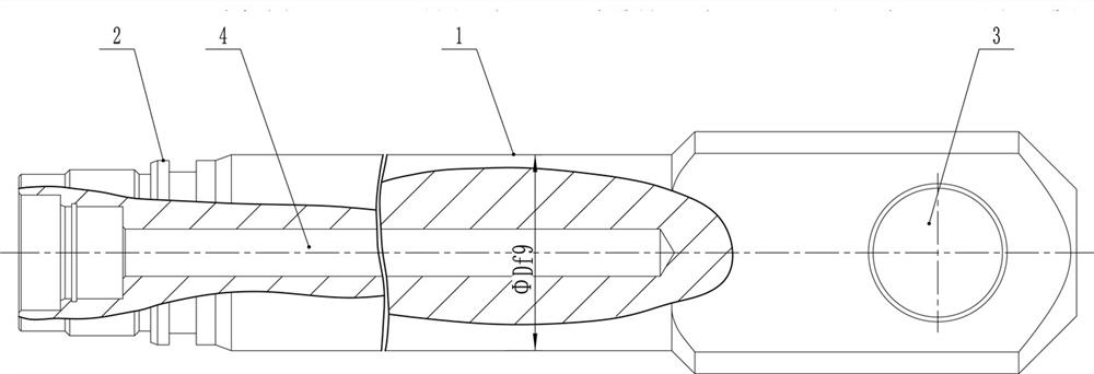
[0032] Such as Figure 1-Figure 3 As shown, a slender piston rod laser cladding deformation control method is used to process a piston rod with an outer circle of φ70mm in the cladding area. In the figure, D refers to the cladding diameter, which includes the following steps:

[0033] Rough turning: Turn out the outline of the slender piston rod, and reserve a size of 78mm. The purpose is to overcome the problem of stress springback after straightening and leave more dimensions for subsequent processing and removal.

[0034] Drill hinge holes 3.

[0035] Quenching and tempering: The slender piston rod workpiece is placed in the furnace vertically and vertically into the tank to avoid mutual extrusion, and the workpiece can move up and down evenly.

[0036] Straightening: Use tools to straighten the slender piston rod to reduce the bendi...


PUM


Abstract

The invention provides a laser cladding deformation control method for a slender piston rod. The laser cladding deformation control method comprises the following steps of rough turning, wherein the reserved size is larger than or equal to phi(D+n) mm; drilling a hinge hole; hardening and tempering; straightening, wherein the jerk value of the slender piston rod is less than or equal to 1mm; Semi-finish turning, wherein the reserved size is larger than or equal to phi(D+n1) mm; finish turning, specifically, carrying out further finish machining on the outer circle of the slender piston rod bytaking a semi-finish-turned outer circle as a benchmark; high-speed laser cladding, specifically, detecting the jerk value of a sealing surface; size detection, specifically, detecting the diameter ofeach part of the slender piston rod; and carrying out milling-flattening, excircle grinding and polishing in order to complete the laser cladding process of the slender piston rod. The laser claddingdeformation control method for the slender piston rod has the advantages that severe workpiece deformation caused by excessive heat generated in the laser cladding process is avoided, and the processflow and time are saved.

Description

technical field [0001] The invention relates to a preparation process of an underground hydraulic support cylinder in a coal mine, in particular to a method for controlling deformation of a slender piston rod by laser cladding. Background technique [0002] The traditional laser cladding technology adopts the method of preset powder feeding (or side-axis powder feeding), and about 80% of the energy acts on the substrate, so that the local deformation of the slender piston rod (length L / diameter D>6) is greater than 3mm. [0003] The workpiece adopts the traditional laser cladding process as follows: blanking - rough turning - drilling hinged holes - quenching and tempering - straightening - semi-finishing turning - finishing turning - traditional laser cladding - size inspection - Finish turning—milling—grinding outer circle—polishing, even if “straightening” correction measures are taken, “straightening” stress rebound will occur during the processing, resulting in local...

Claims


Application Information

Patent Timeline
Patent Type & Authority Applications(China)
IPC IPC(8): B23P15/00C23C24/10
CPCB23P15/00C23C24/10
Inventor 付祖冈李福永程相榜白海明刘晟张自强屈海燕汤利利张海生印文才张静
Owner ZHENGZHOU COAL MINING MACHINERY GRP
Why Eureka
Eureka Blog
Learn More