Quick replacement device and replacement method for continuous casting ladle tank protective sleeve pipe

A technology for protecting sleeves and continuous casting steel, which is applied in foundry equipment, casting melt containers, metal processing equipment, etc., and can solve the problems of wasting materials, easily damaged equipment, and low work efficiency.

Pending Publication Date: 2020-12-08
成都尚威耐火材料有限公司
View PDF0 Cites 0 Cited by
  • Summary
  • Abstract
  • Description
  • Claims
  • Application Information

AI Technical Summary

Problems solved by technology

The process of molten steel entering the ladle tank from the steelmaking furnace is usually staged, and the temperature of the molten steel is relatively high, causing the protective casing to be subjected to a staged high and low temperature. After multiple high and low temperatures, the upper and lower ports of the protective casing are prone to Cracks or damage from thermal expansion and cold contraction, requiring replacement at any time
[0003] At present, there is no more reliable equipment for the replacement of the protective sleeve, and the equipment is easily damaged. Manual replacement needs to withstand high temperatures, and the work efficiency is low. The replacement is the replacement of the entire protective sleeve, which wastes materials and resources.

Method used


Image

  • Quick replacement device and replacement method for continuous casting ladle tank protective sleeve pipe
  • Quick replacement device and replacement method for continuous casting ladle tank protective sleeve pipe
  • Quick replacement device and replacement method for continuous casting ladle tank protective sleeve pipe

Examples


Embodiment 1

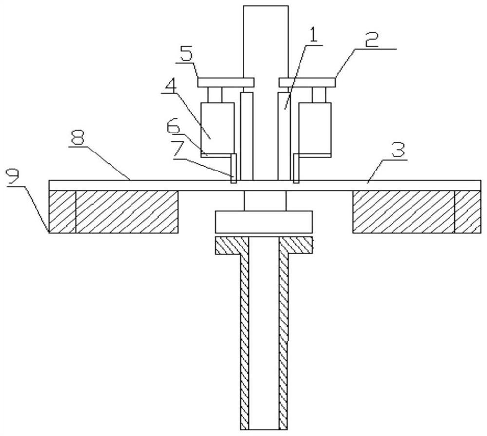
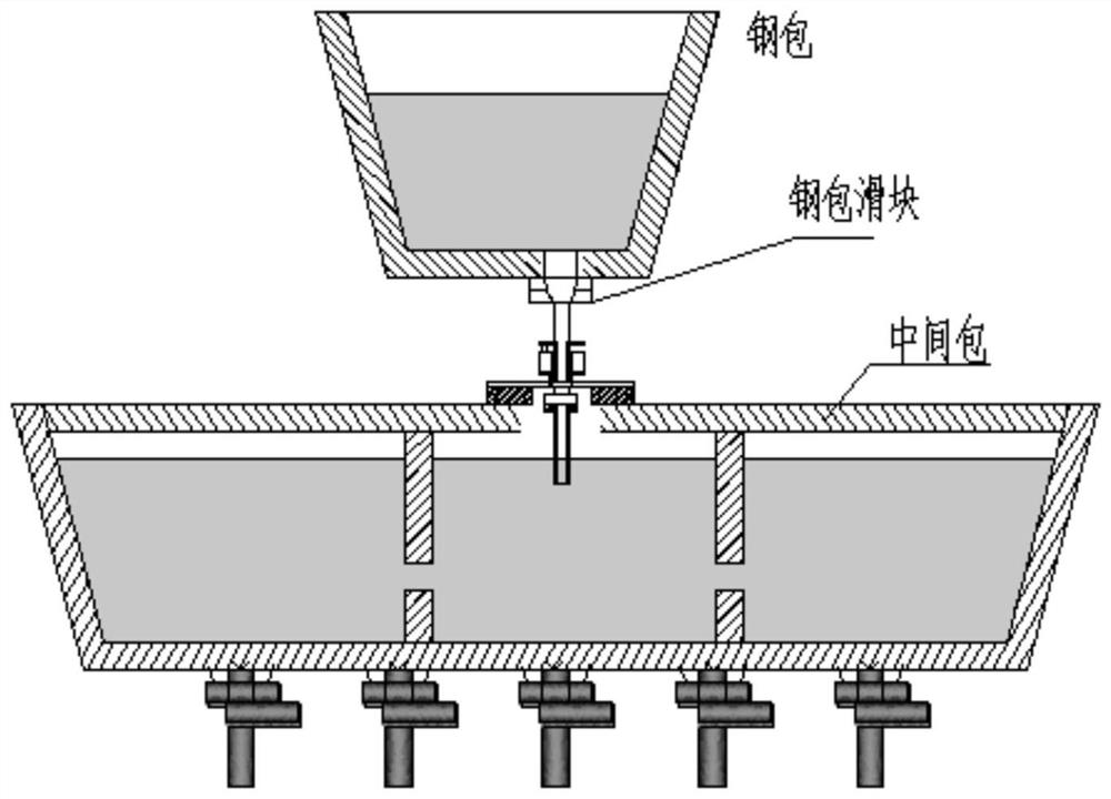
[0028] according to figure 1 , figure 2 As shown, the continuous casting ladle tank protective casing quick replacement device is applied above or below the continuous casting ladle tank, including surrounding pipe 1, lifting device 2, and base 3;

[0029] The surrounding tube 1 is two arc tube pieces;

[0030] The lifting device 2 includes a cylinder 4, an upper plate 5, a lower plate 6, and a pillar 7, the cylinder 4 is located between the upper plate 5 and the lower plate 6, and the pillar 7 supports the lower plate 6;

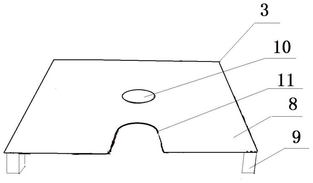
[0031] The base 3 includes a base plate 8, a leg 9, and a circular opening 10, and the leg 9 supports the base plate 8;

[0032] The upper end of the surrounding tube 1 is connected to the upper plate 5 of the lifting device 2 , the lower end of the surrounding tube 1 is connected to the bottom plate 8 of the base 3 , and the lower end of the surrounding tube 1 surrounds a circular opening 10 .

[0033] In the above setting, the surrounding tube 1 can f...

Embodiment 2

[0035] according to figure 1 , figure 2 As shown, the cylinder 4 is a pneumatic cylinder or a hydraulic cylinder.

[0036] In the above arrangement, the pneumatic cylinder or hydraulic cylinder can adjust the lifting and control the surrounding pipe.

Embodiment 3

[0038] according to figure 1 , figure 2 As shown, the bottom plate 8 is provided with an observation port 11 at the edge, so that the replacement situation can be observed.

[0039] In the above setting, the observation port 11 can observe the replacement situation and the ladle situation at any time.


PUM


Abstract

The invention relates to the field of iron and steel smelting technical devices, in particular to a quick replacement device and replacement method for a continuous casting ladle tank protective sleeve pipe. The quick replacement device comprises a surrounding pipe (1), a lifting device (2) and a base (3). A protective sleeve pipe can be quickly replaced, simpleness and convenience are achieved, time waste caused by protective sleeve pipe replacement to the continuous casting process is avoided, and time is saved; due to the ingenious design, only the damaged part of the protective sleeve pipeis replaced, the replacement cost of the protective sleeve pipe is reduced, the use cost of refractory materials is reduced, and meanwhile the working efficiency is greatly improved.

Description

technical field [0001] The invention relates to the field of technical devices for iron and steel smelting, and more specifically, relates to a rapid replacement device and a replacement method for a continuous casting ladle tank protection sleeve. Background technique [0002] After the molten steel is smelted in the electric furnace, it is directly poured or injected into the ladle tank, and then transferred from the ladle tank to the next process. In the process, the molten steel is usually protected by a protective sleeve. The upper end of the protective sleeve is connected to the ladle nozzle, the molten steel flowing out from the ladle directly contacts the upper end of the protective sleeve, and the molten steel flows into the ladle tank or tundish from the lower end of the protective sleeve, and the lower end of the protective sleeve usually extends into the ladle tank Or the inside of the tundish, after the ladle tank or tundish is filled with molten steel, the mol...

Claims


Application Information

Patent Timeline
IPC IPC(8): B22D41/56
CPCB22D41/56
Inventor 卿志明卿晓巍
Owner 成都尚威耐火材料有限公司
Why Eureka
Try Eureka