Concrete aggregate precooling device

A concrete aggregate and pre-cooling technology, which is applied to clay preparation devices, household refrigeration devices, mixed operation control devices, etc., can solve the problem of increasing the direct cost of primary air cooling, the large amount of gold deposits used in steel structures, and the complex ice-making process. And other issues

Active Publication Date: 2020-12-04
石门县山力建材有限责任公司
View PDF7 Cites 0 Cited by
  • Summary
  • Abstract
  • Description
  • Claims
  • Application Information

AI Technical Summary

Problems solved by technology

Large-volume concrete projects are often located in alpine and canyon areas with complex terrain. The site leveling and excavation required to build a primary air-cooled silo is extremely large, which further increases the direct cost of primary air-cooling
The production of flake ice needs to set up an ice-making building, which has complex processes, many equipments, and a large amount of gold knots for steel structures

Method used


Image

  • Concrete aggregate precooling device
  • Concrete aggregate precooling device
  • Concrete aggregate precooling device

Examples


Embodiment 1

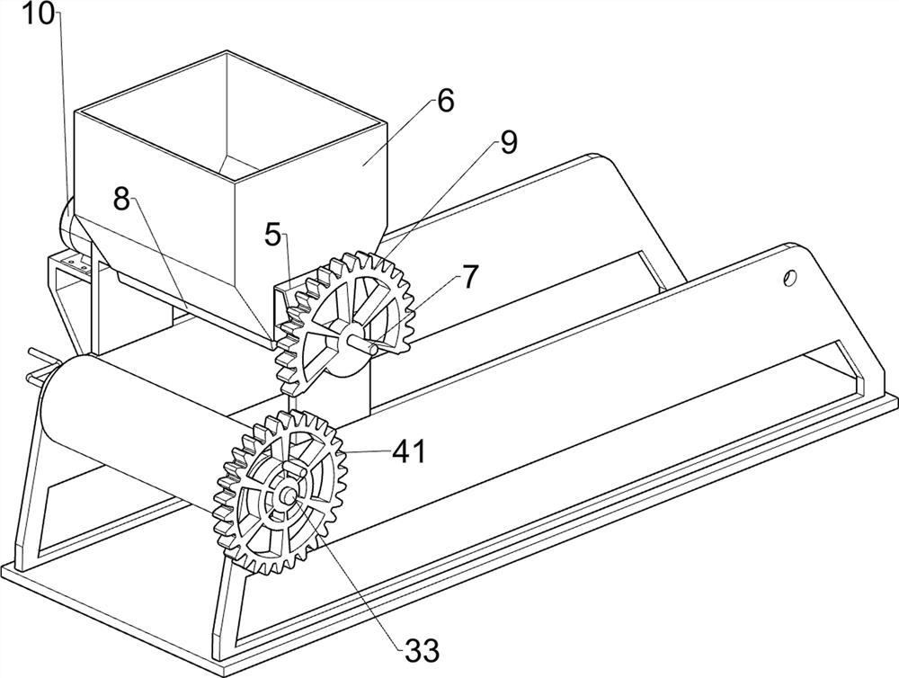
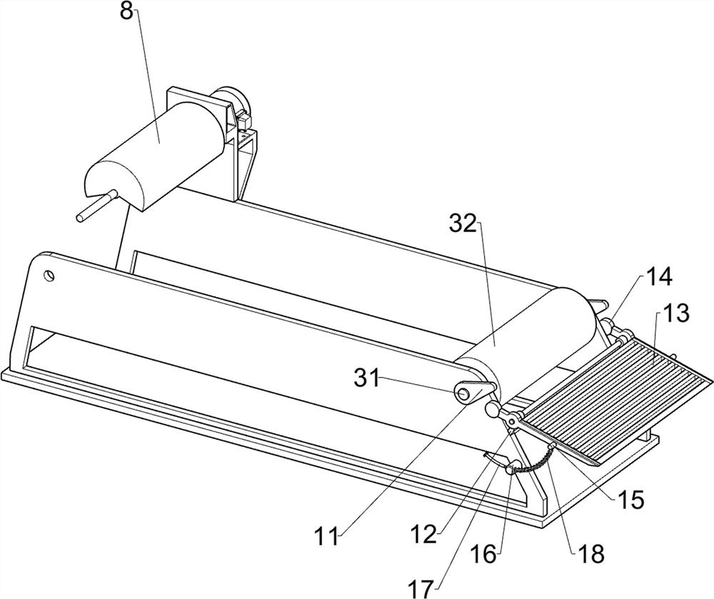
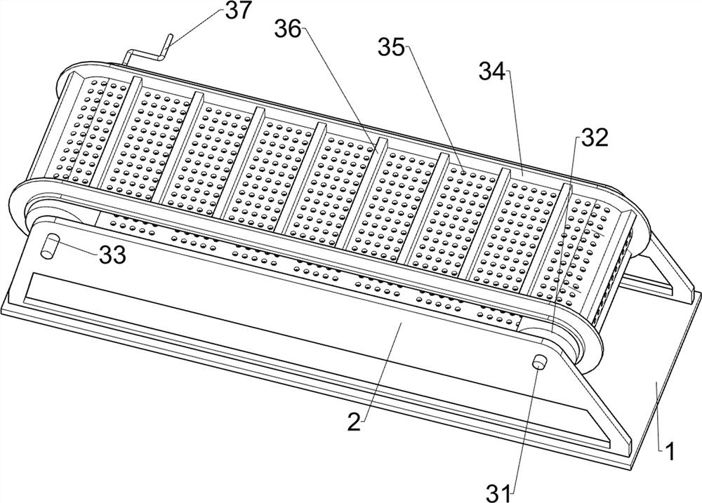
[0022] A concrete aggregate precooling device, such as figure 1 , figure 2 , image 3 , Figure 4 and Figure 5 As shown, it includes a base 1, a support plate 2, a transmission device 3 and a pre-cooling device 4. The top of the base 1 is fixedly connected with a support plate 2 symmetrically front and rear, a transmission device 3 is provided between the support plates 2, and a transmission device 3 is provided on the support plate 2. Pre-cooling device 4.

[0023] When people need to use this device, first people connect the pre-cooling device 4 to the water pipe, then place the collecting tool on the right side of the conveying device 3, then turn the conveying device 3 to make the conveying device 3 operate, and the conveying device 3 drives the pre-cooling The device 4 works, and then people can pour the aggregate on the left side of the conveying device 3 at intervals, and the conveying device 3 operates to convey the aggregate to the right. When the aggregate move...

Embodiment 2

[0029] On the basis of Example 1, such as Figure 4 and Figure 5As shown, it also includes a second support block 5, a charging box 6, a second rotating shaft 7, a cylindrical missing block 8, a missing gear 9 and a servo motor 10, and the top of the left side of the supporting plate 2 is fixedly connected with a second supporting block 5. A charging box 6 is arranged between the second supporting blocks 5, and the lower part of the charging box 6 is provided with a second rotating shaft 7 in a rotating manner, and the second rotating shaft 7 is rotationally connected with the second supporting blocks 5 on both sides. The second rotating shaft 7 is provided with a cylindrical missing block 8, and the cylindrical missing block 8 is positioned at the inner side of the bottom of the charging box 6. The front end of the second rotating shaft 7 is provided with a missing gear 9, and the missing gear 9 meshes with the circular gear 41. A servo motor 10 is installed between the sec...


PUM


Abstract

The invention relates to a precooling device, in particular to a concrete aggregate precooling device. The concrete aggregate precooling device is simple in structure, capable of quickly cooling aggregate and small in water consumption. The concrete aggregate precooling device comprises a base, wherein supporting plates are symmetrically arranged at the top of the base; a conveying unit, wherein the conveying unit is arranged between the supporting plates; and a precooling unit, wherein the precooling unit is arranged on the supporting plates. Rotation of the conveying belt is achieved by rotating a handle, then through cooperation of the conveying unit and the precooling unit, water is scattered by the precooling unit when aggregate moves rightwards, the aggregate is rapidly cooled, intermittent water scattering of a sprinkler is achieved through left-right movement of a guide pipe, and then water is saved. A servo motor is started to drive a cylindrical notch block to rotate, and then intermittent discharging of aggregate and automatic conveying of the conveying unit are achieved.

Description

technical field [0001] The invention relates to a precooling device, in particular to a concrete aggregate precooling device. Background technique [0002] Aggregate, also known as aggregate, is a granular material that acts as a skeleton and filling in concrete and mortar. Commonly used aggregates are crushed stone and pebble. Due to the short time available for pouring concrete under natural conditions, it is restricted normal construction time. [0003] In order to meet the normal construction of concrete under the high temperature construction conditions in summer, technological measures must be taken to pre-cool the concrete. At present, aggregate air cooling, adding flake ice and cold water mixing are common pre-cooling technologies for the production of pre-cooled concrete. In large hydropower stations It has been widely used in the construction of large-volume concrete projects such as engineering. Aggregate air cooling can be subdivided into ground air cooling and...

Claims


Application Information

Patent Timeline
Patent Type & Authority Applications(China)
IPC IPC(8): B28C7/00F25D1/02
CPCB28C7/0038F25D1/02
Inventor 刘志向
Owner 石门县山力建材有限责任公司
Why Eureka
Try Eureka