
Microfluidic chip for bacterial lysis, bacterial lysis device and application of bacterial lysis device

A microfluidic chip and bacteria technology, applied in the field of cell biology, can solve problems such as the complex structure of the lysing device, and achieve the effects of continuous and controllable lysing process, efficient bacterial lysing, and simple manufacturing process

Pending Publication Date: 2020-12-01
JILIN UNIV
View PDF8 Cites 0 Cited by
  • Summary
  • Abstract
  • Description
  • Claims
  • Application Information

AI Technical Summary

Problems solved by technology

However, the current research on electrolysis still has the limitation of the complex structure of the cracking device.

Method used


Image

  • Microfluidic chip for bacterial lysis, bacterial lysis device and application of bacterial lysis device
  • Microfluidic chip for bacterial lysis, bacterial lysis device and application of bacterial lysis device
  • Microfluidic chip for bacterial lysis, bacterial lysis device and application of bacterial lysis device

Examples


Embodiment 1

[0059] Embodiment 1 A kind of method of escherichia coli cracking

[0060] Step 1: Design and fabrication of microfluidic chip

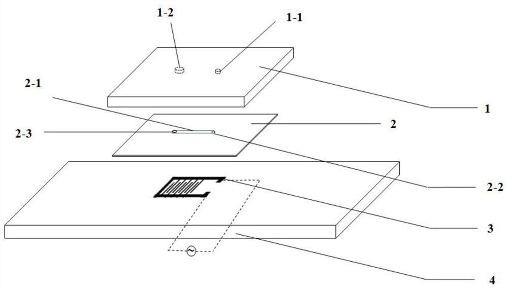
[0061] Schematic diagram of the structure of the microfluidic chip figure 1 shown.

[0062] From top to bottom:

[0063] The first layer is an acrylic cover plate 1, on which holes are drilled with a drill, which are respectively the sample inlet 1-1 and the sample outlet 1-2, and the distance between the sample inlet 1-1 and the sample outlet 1-2 is The length of the microchannel 2-1. It is tightly covered on the upper layer of the microchannel 2-1, and the positions of the sample inlet 1-1 and the sample outlet 1-2 are in one-to-one correspondence with the microchannel inlet 2-2 and the microchannel outlet 2-3.

[0064] The second layer uses 3M double-sided tape 2 to etch the microchannel 2-1. Take another glass slide, spray it with alcohol and wipe it clean, take a certain length of 3M double-sided tape and stick it on it, and use a scalpel t...


PUM

PropertyMeasurementUnit
lengthaaaaaaaaaa
widthaaaaaaaaaa
depthaaaaaaaaaa

Abstract

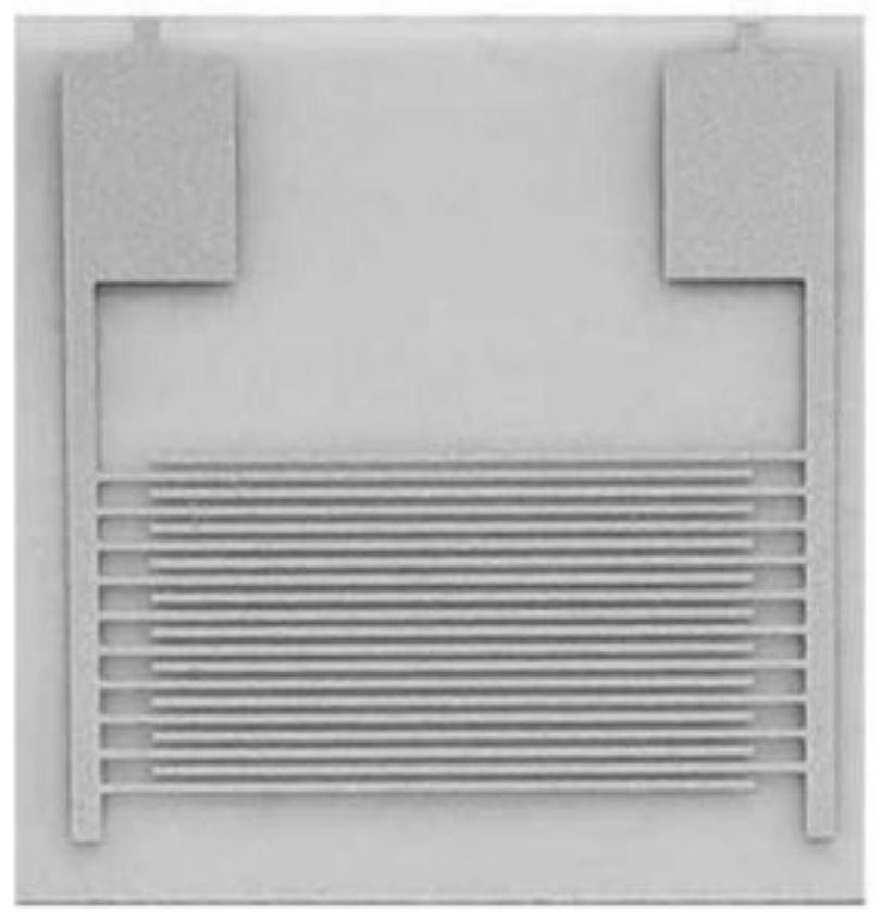
The invention provides a micro-fluidic chip for bacterial lysis, a bacterial lysis device and application of the bacterial lysis device, and belongs to the technical field of cell biology. The chip isof a three-layer laminated structure, and from top to bottom, a first layer is an acrylic cover plate 1, a second layer is a 3M double faced adhesive tape 2, and a third layer is a glass slide 4; andan interdigital electrode 3 is fixed on the glass slide 4. The micro-fluidic chip disclosed by the invention can be used for cracking bacteria in a pure electric field, and compared with a widely used chemical method (such as an alkali cracking method) for cracking bacteria at present, the method disclosed by the invention does not need to add any chemical reagent, so that damage of the chemicalreagent to bacterial cell contents and subsequent operation of removing the chemical reagent are avoided, and the method is more convenient. The micro-fluidic chip disclosed by the invention is simplein manufacturing process and low in cost. The chip disclosed by the invention avoids the defects of high price and the like caused by using materials such as polydimethylsiloxane (PDMS), is small inproduct size and convenient to carry, and can completely realize bacterial electrolysis in function.

Description

technical field [0001] The invention relates to the technical field of cell biology, in particular to a microfluidic chip for lysing bacteria, a lysing device for bacteria and applications thereof. Background technique [0002] Microfluidics (Microfluidics) refers to the science and technology involved in the use of micropipes (tens to hundreds of microns in size) to process or manipulate tiny fluids (nanoliters to attic liters in volume). , fluid physics, microelectronics, new materials, emerging interdisciplinary disciplines of biology and biomedical engineering. [0003] At present, some studies have applied microfluidic technology to electrolysis of bacteria. Poudineh et al. used a three-dimensional tip electrode (3DSTE) to lyse Escherichia coli, and achieved the release of biomarker RNA, and at the same time determined and optimized the conditions for bacterial lysis under the electrode (Poudineh M, Mohamadi RM, Sage A, Mahmoudian L, Sargent EH, KelleySO. Three-dimens...

Claims


Application Information

Patent Timeline
Patent Type & Authority Applications(China)
IPC IPC(8): C12M1/33C12M1/42C12M1/00C12N1/06
CPCC12M23/16C12M47/06C12N1/066
Inventor 杨方李桂英赵舰秋张影方蛟
Owner JILIN UNIV
Learn More