Combined die
A combined mold and mold technology, which is applied in the direction of manufacturing tools, casting molding equipment, casting molds, etc., can solve the problems of long mold development cycle, non-repeatable use, complex casting molds, etc., and achieve convenient and fast manufacturing, weight reduction, and shape accuracy high effect
- Summary
- Abstract
- Description
- Claims
- Application Information
AI Technical Summary
Problems solved by technology
Method used
Image

Examples
Embodiment 1
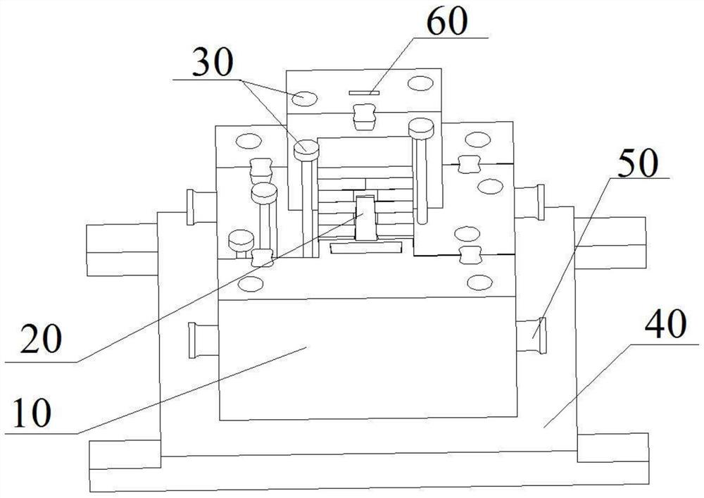
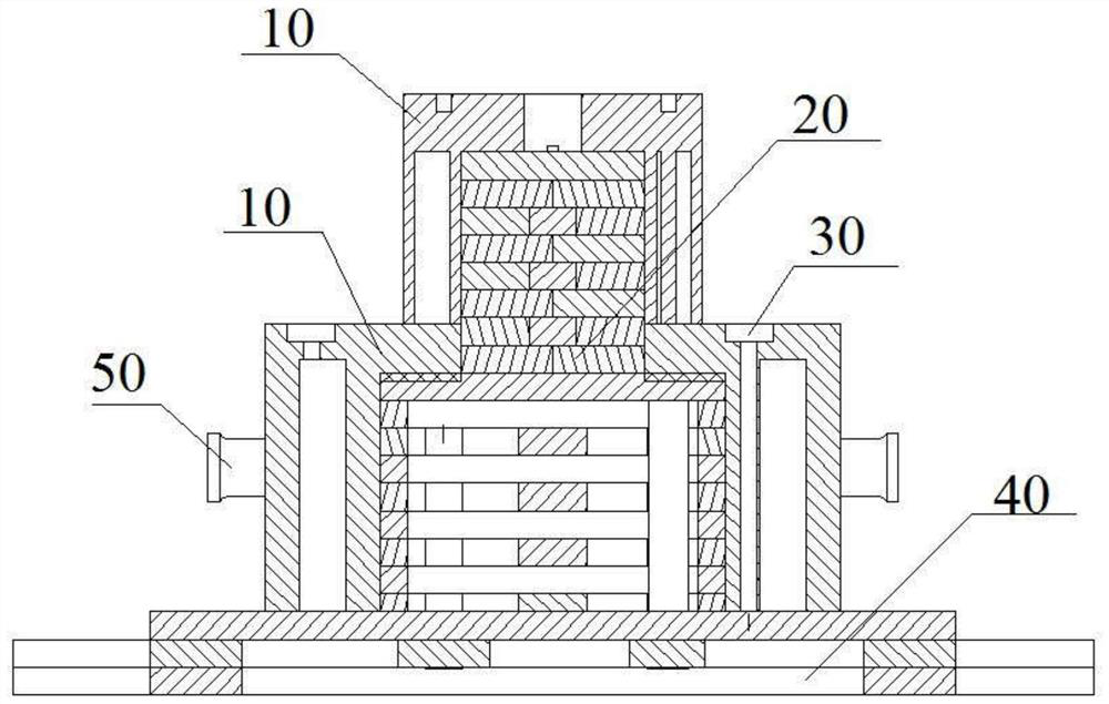
[0061] A combined mould, comprising a follow-up die 10, a support die 20 and a riveting rod 30, the follow-up die 10 includes a main body 11, a reinforcement layer 12, a working surface 13 and an assembly face 14, the main body 11 is formed by pressing or printing granular materials The reinforcement layer 12 is arranged on the surface of the main body 11, or the reinforcement layer 12 penetrates into the surface of the main body 11. The side of the main body 11 in contact with the sand mold cavity is the working surface 13, and the opposite side is the assembly surface 14. The support mold 20 is installed on the main body 11. One side of the assembly surface 14, and the shape matches the shape of the assembly surface 14, because some of the molds are used to form the external structure of the casting such as attached Figure 10-13 As shown, some are to form the inner cavity structure of the casting as attached Figure 1-9 As shown, so there will be differences, but in a word,...
Embodiment 2
[0070] On the basis of embodiment 1, with reference to the attached Figure 3-6 As shown, the main body 11 also includes reinforcing ribs 113, the main body 11 is made of double layers, the main body 11 is a double or multi-layer sandwich with a cavity, and a reinforcing rib 113 is arranged between the two-layer structure, the described Both ends of the reinforcing rib 113 are respectively connected to the two-layer structure, and the double or multiple layers are integrally formed with the reinforcing rib 113 . The wall thickness of each layer is 20-50 mm. The spacing of the ribs 113 is 100-300 mm.
[0071]After the main body 11 is made into two or more layers, the reinforcement layer 12 is adhered or infiltrated on the surface to obtain the follow-up mold 10, which reduces the quality of the main body 11 and increases the area of the reinforcement layer 12, thus improving the strength of the follow-up mold 10. The overall hardness and tensile strength can obtain a confor...
Embodiment 3
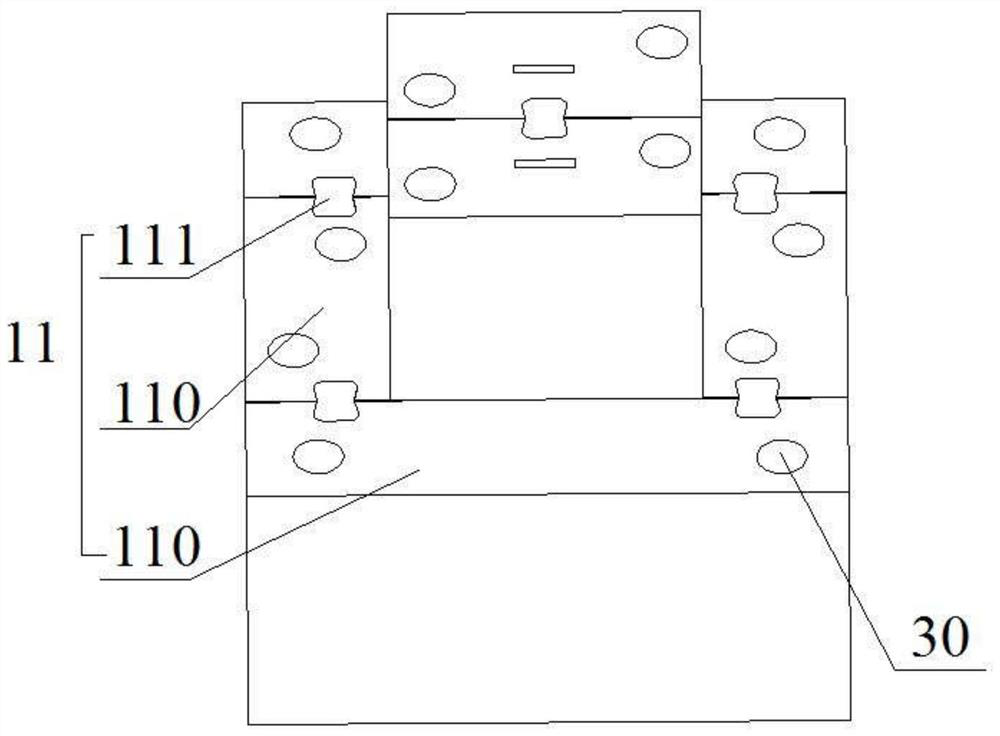
[0073] On the basis of Embodiment 1 or Embodiment 2, the main body 11 includes a splicing body 110, a connecting block 111, and a slot 112. The main body 11 is formed by splicing at least two splicing bodies 110; Two adjacent splicing bodies 110 are connected, and at least two splicing bodies 110 are relatively fixed. Adjacent splicing bodies 110 are respectively provided with matching protruding or recessed slots 112 , that is, the adjacent splicing bodies 110 are spliced and formed by placing the protrusions in the recesses.
[0074] Refer to attached figure 1 And attached image 3 As shown, the adjacent splicing bodies 110 are connected together by connecting blocks 111 or card slots 112, so that the splicing bodies 110 become a whole. Generally, the butterfly-shaped or flower-shaped connecting blocks 111 are arranged horizontally, and the splicing bodies 110 are connected vertically. On the straight side, the splicing body 110 is connected to the splicing body 110 thro...
PUM
| Property | Measurement | Unit |
|---|---|---|
| Tensile strength | aaaaa | aaaaa |
| Thickness | aaaaa | aaaaa |
| Tensile strength | aaaaa | aaaaa |
Abstract
Description
Claims
Application Information
 - R&D
- Intellectual Property
- Life Sciences
- Materials
- Tech Scout
- Unparalleled Data Quality
- Higher Quality Content
- 60% Fewer Hallucinations
Browse by: Latest US Patents, China's latest patents, Technical Efficacy Thesaurus, Application Domain, Technology Topic, Popular Technical Reports.
© 2025 PatSnap. All rights reserved.Legal|Privacy policy|Modern Slavery Act Transparency Statement|Sitemap|About US| Contact US: help@patsnap.com