
Torque ripple suppression method for direct-drive wind turbine generator

A wind turbine, torque ripple technology, applied in motor control, motor generator control, AC motor control, etc., can solve problems such as inverter nonlinearity, large electromagnetic torque ripple, and large harmonics in stator current. To achieve the effect of stable operation process and strong practicability

Active Publication Date: 2020-11-24
SHENYANG POLYTECHNIC UNIV
View PDF5 Cites 5 Cited by
  • Summary
  • Abstract
  • Description
  • Claims
  • Application Information

AI Technical Summary

Problems solved by technology

In addition, during the operation of the generator, due to the uneven distribution of the air gap magnetic field or the nonlinear characteristics of the inverter, there are a large number of harmonics in the stator current, which will generate large electromagnetic torque ripples at low speeds, which will be generated through the transmission shaft. to the load, becoming a major hidden danger to the safe operation of wind turbines

Method used


Image

  • Torque ripple suppression method for direct-drive wind turbine generator
  • Torque ripple suppression method for direct-drive wind turbine generator
  • Torque ripple suppression method for direct-drive wind turbine generator

Examples


Embodiment Construction

[0060] The specific implementation manners of the present invention will be further described in detail below in conjunction with the accompanying drawings and embodiments. The following examples are used to illustrate the present invention, but are not intended to limit the scope of the present invention.

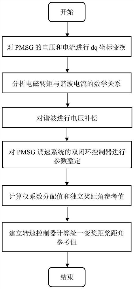
[0061] A direct-drive wind turbine torque ripple suppression method, such as figure 1 shown, including the following steps:

[0062] Step 1: by performing dq rotation coordinate transformation on the voltage and current of the permanent magnet synchronous generator (PMSG);

[0063] The mathematical relationship equations of the voltage and current of PMSG in the dq synchronous rotating coordinate system are:

[0064]

[0065] Among them, i d and i q Respectively d-axis and q-axis current; u d and u q Respectively d-axis and q-axis voltage; R s is the stator resistance; ω is the electrical angular frequency of the generator; L d and L q are d-axis and q-axis ind...


PUM


Abstract

The invention provides a torque ripple suppression method for a direct-drive wind turbine generator, and relates to the technical field of wind power generation. The method comprises: for electromagnetic torque pulsation, using a harmonic voltage compensation suppression method: using a low-pass filter to extract a higher harmonic current component, calculating and superposing a harmonic voltage compensation value to a reference voltage, and the harmonic component being offset; for aerodynamic torque pulsation, using an independent variable pitch control method, establishing a weight coefficient distributor, calculating pitch angles corresponding to different blades through a mathematical model of weight coefficient distribution and acting on a variable pitch mechanism, and aerodynamic torque pulsation caused by pitch angle pulsation being reduced; and finally, on the basis of a harmonic voltage compensation method, arranging a rotating speed controller, the difference value between the actual rotating speed and the rated rotating speed of a generator serving as a deviation value and being introduced into the input end of the rotating speed controller, the output end of the rotating speed controller being a unified pitch angle reference value, and then achieving the cooperative suppression of pneumatic torque pulsation and electromagnetic torque pulsation in combination with anindependent variable pitch control method.

Description

technical field [0001] The invention relates to the technical field of wind power generation, in particular to a method for suppressing torque ripple of a direct-drive wind turbine. Background technique [0002] Wind turbines have experienced two stages of constant speed and constant frequency and variable speed and constant frequency. In the constant speed and constant frequency stage, the speed of the wind turbine unit remains constant during operation and outputs stable alternating current. The advantage of this mode of operation lies in its simple structure and high reliability, but due to the limitation of constant rotation speed and constant change of wind speed, the utilization rate of wind energy is generally low. The variable speed and constant frequency stage is based on the constant speed and constant frequency. The generator speed is variable and can still output stable alternating current. Due to its variable speed, variable speed and constant frequency make t...

Claims


Application Information

Patent Timeline
Patent Type & Authority Applications(China)
IPC IPC(8): H02P21/05H02P21/22H02P21/20H02P21/14H02P29/50H02P6/182H02P25/024H02P27/12H02P21/00
CPCH02P6/182H02P21/0003H02P21/05H02P21/14H02P27/12H02P21/20H02P21/22H02P25/024H02P29/50
Inventor 王湘明张佳美仲奇奇郑浩
Owner SHENYANG POLYTECHNIC UNIV
Learn More